Aging chamber entrance device

An aging room and entrance technology, applied in nonlinear optics, instruments, optics, etc., can solve problems affecting the maintenance of clean room constant temperature, constant pressure or constant humidity environment, waste of energy, and energy waste, so as to improve the efficiency of aging testing , the effect of saving electric energy

Inactive Publication Date: 2009-11-18
AU OPTRONICS (SUZHOU) CORP LTD +1
View PDF3 Cites 0 Cited by
  • Summary
  • Abstract
  • Description
  • Claims
  • Application Information

AI Technical Summary

Problems solved by technology

When transporting the liquid crystal module into the opening 80, due to the effect of pressure relief, the cold air in the clean room will flow into the aging room and reduce the internal temperature of the aging room, even lower than the set minimum test temperature, thereby affecting the affected Measure the efficiency and accuracy of the aging test of the liquid crystal module; at the same time, in order to keep the temperature in the aging room within a set range, it is necessary to continuously provide energy to make the air conditioner in the aging room heat up and run. If cold air flows into the aging room, it will decrease internal temperature of the aging chamber, thus wasting energy
On the contrary, the hot air in the aging room will also flow into the clean room, affecting the maintenance of the clean room's constant temperature, constant pressure or constant humidity environment, resulting in unnecessary waste of energy
[0006] As mentioned above, the existing aging room opening design has some inconvenience and defects in use, so it is extremely necessary to design a new aging room entrance device to effectively isolate the air circulation inside and outside the aging room

Method used


Image

  • Aging chamber entrance device
  • Aging chamber entrance device
  • Aging chamber entrance device

Examples


Embodiment Construction

[0024] The detailed description and technical content of the present invention are now described as follows in conjunction with the accompanying drawings. The following descriptions of the various embodiments refer to the accompanying figures to illustrate specific embodiments in which the invention may be practiced. The direction terms mentioned in the present invention, such as "upper", "lower", "left", "right", "horizontal", "vertical", etc., are only referring to the directions attached to the drawings. Accordingly, the directional terms used are illustrative, not limiting, of the invention.

[0025] In the following embodiments, the same parts are denoted by the same symbols in different drawings.

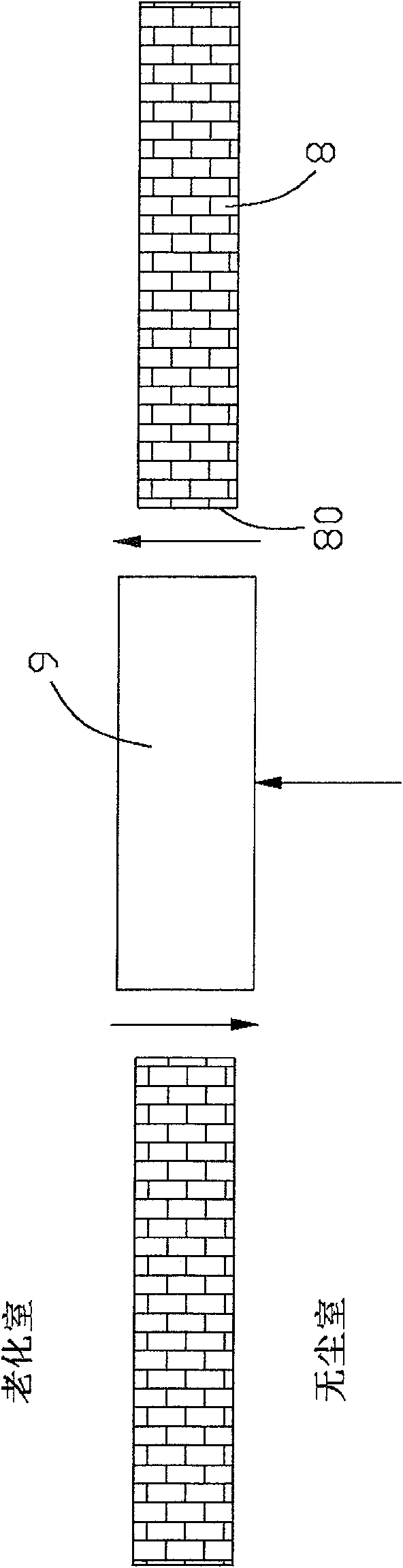
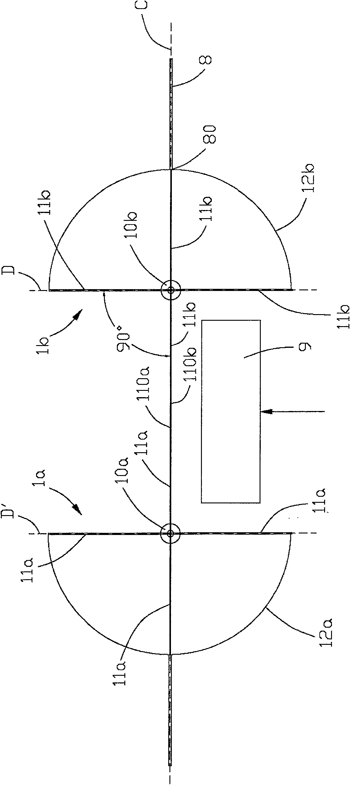
[0026] figure 2 It is a schematic top view of the inlet device of the aging chamber according to the first preferred embodiment of the present invention, showing that the inlet device of the aging chamber is in a closed state. The entrance device of the aging chamber is ar...


PUM

PropertyMeasurementUnit
angleaaaaaaaaaa

Abstract

An inlet device for an aging chamber, comprising two opposite rotating bodies located on the same transverse center line, each rotating body has a rotating shaft, at least one cam arranged on the end of the rotating shaft, for abutting against the cam At least one abutting piece, and several door faces connected to the rotating shaft on one side. When the inlet device is in a closed state, the abutting member abuts against the groove provided on the side of the cam, restricting the opposite sides of each of the door surfaces of the two rotating bodies to abut against each other; when the inlet device is in an open state for a When the vehicle enters, each of the aforementioned opposite sides of the two opposite door surfaces is kept in contact with the side edge of the vehicle. Therefore, the inlet device of the present invention can effectively isolate the internal and external air circulation of the aging chamber, thereby saving energy and improving the aging test efficiency.

Description

technical field [0001] The invention relates to an inlet device, in particular to an inlet device of an aging room, which can effectively isolate the internal and external air circulation of the aging room, save energy and improve the aging test efficiency. Background technique [0002] The production process of a liquid crystal display (LCD, Liquid Crystal Display) generally includes an array (Array) process at the front end, a cell assembly process at the middle end, and a module (Module) process at the rear end. In the later stage of the module process, the assembled LCD panel is matched with a driver IC and a circuit board, and assembled with a backlight source and an iron frame to form a liquid crystal module. The entire process of the above-mentioned module process must be carried out on a module production line in a clean room to prevent impurities from entering the liquid crystal module and affecting the quality of the finished product. Due to the needs of the modul...

Claims


Application Information

Patent Timeline
Patent Type & Authority Patents(China)
IPC IPC(8): G02F1/13G09G3/20G09G3/36
Inventor 张良许金建邹友明
Owner AU OPTRONICS (SUZHOU) CORP LTD
Why Eureka
Try Eureka