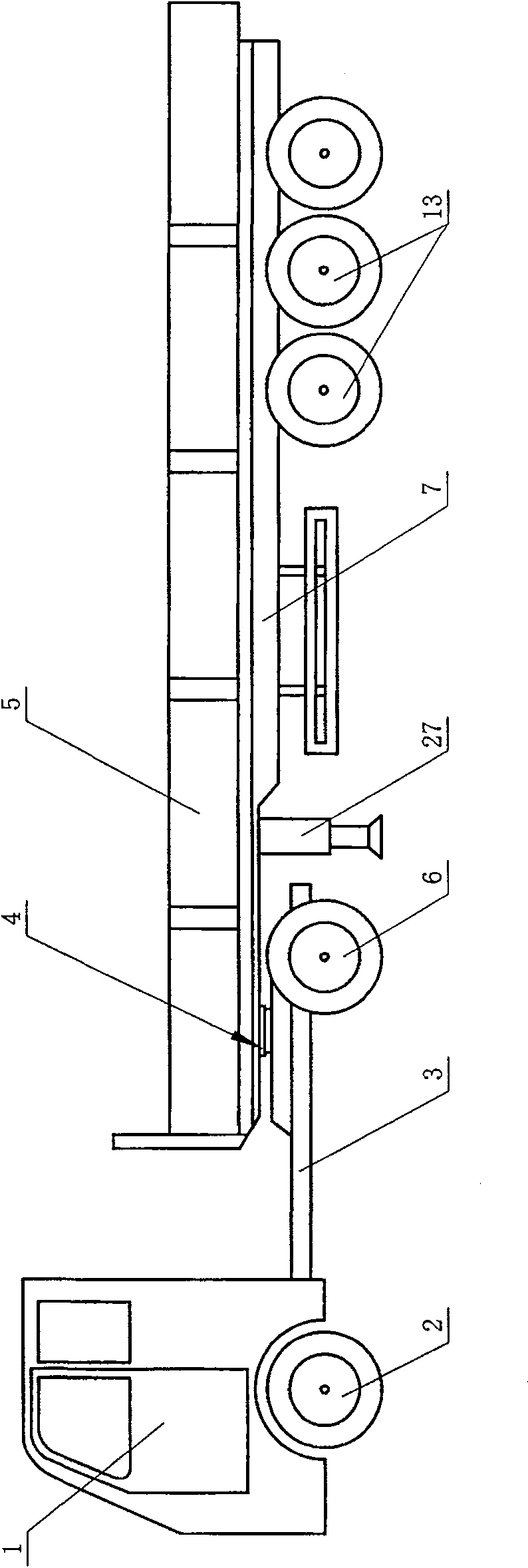
Semi-trailer with automatic synchronization steering mechanism
A steering mechanism and automatic synchronization technology, which is applied to steering mechanisms, trailer steering mechanisms, and steering mechanisms of front and rear tandem vehicles. Different problems, affecting the service life of the trailer, etc., to achieve the effect of facilitating the promotion and implementation, avoiding sliding friction, simple and novel structure
- Summary
- Abstract
- Description
- Claims
- Application Information
AI Technical Summary
Problems solved by technology
Method used
Image
Examples
Embodiment 1
[0038] Embodiment one: see Figure 1-Figure 6 , a semi-trailer with an automatic synchronous steering mechanism, comprising a main vehicle 1, a traction girder 3 connected to the main vehicle 1 and a power wheel 6 on the traction girder 3, the traction girder 3 moves with the semi-trailer 5 through a rotating connection device 4 Connected, installed on the rear end of the bottom of the semi-trailer beam 7, there is a semi-trailer load-bearing wheel 8, and a front load-bearing wheel 13 of the semi-trailer is installed on the front end of the bottom of the semi-trailer beam 7, and the front load-bearing wheel 13 of the semi-trailer is installed on the semi-trailer through the load-bearing wheel rotating mechanism 9 At the bottom of the trailer girder 7, a synchronous steering mechanism 11 driven by gears is connected between the traction girder 3 and the front bearing wheel rotating mechanism 9.
[0039] The load-bearing wheel rotating mechanism 9 is a rotatable structure fixed ...
Embodiment 2
[0043] Embodiment two: see Figure 7 , Figure 8 , the numbering is the same as in Embodiment 1, the meaning is the same, and will not be repeated. The difference is that the radius of the guide wheel 18 becomes larger, the radius of the main wheel gear 17 and the turning mechanism gear 19 are reduced, and the turning mechanism gear 19 wheels become a full circle .
Embodiment 3
[0044] Embodiment three: see Figure 9 , Figure 10 , the numbering is the same as in Embodiment 1, the meaning is the same, and will not be repeated. The difference is that the longitudinal section of the fixed traction pin 15 at the bottom of the semi-trailer beam is a "child"-shaped structure, and the concave hole on the traction disc is in the same shape as the "child". The maximum outer diameter of the "structure is matched, and a fixable stop ring 34 is provided at the edge of the concave hole of the traction disc. After the stop ring 34 is installed in place, it is fixed with fixing bolts 35 around it. The circumferential flange 37 of the traction pin 15 with a "child"-shaped longitudinal section is matched and installed in the annular concave edge 38 formed by the traction disc 10 and the retaining ring 34, and the traction disc 10 can rotate along the axis of the traction pin 15.
PUM
 Abstract
Description
Claims
Application Information
 - R&D Engineer
- R&D Manager
- IP Professional
- Industry Leading Data Capabilities
- Powerful AI technology
- Patent DNA Extraction
Browse by: Latest US Patents, China's latest patents, Technical Efficacy Thesaurus, Application Domain, Technology Topic, Popular Technical Reports.
© 2024 PatSnap. All rights reserved.Legal|Privacy policy|Modern Slavery Act Transparency Statement|Sitemap|About US| Contact US: help@patsnap.com


