Folding device
A technology of folding device and hollow shaft, which is applied to foldable bicycles, transportation and packaging, motor vehicles, etc., can solve the problems of slow folding speed, inconvenient folding operation, complex structure, etc., and achieve strong versatility and high speed And the effect of convenient performance and simple structure
- Summary
- Abstract
- Description
- Claims
- Application Information
AI Technical Summary
Problems solved by technology
Method used
Image
Examples
Embodiment 1
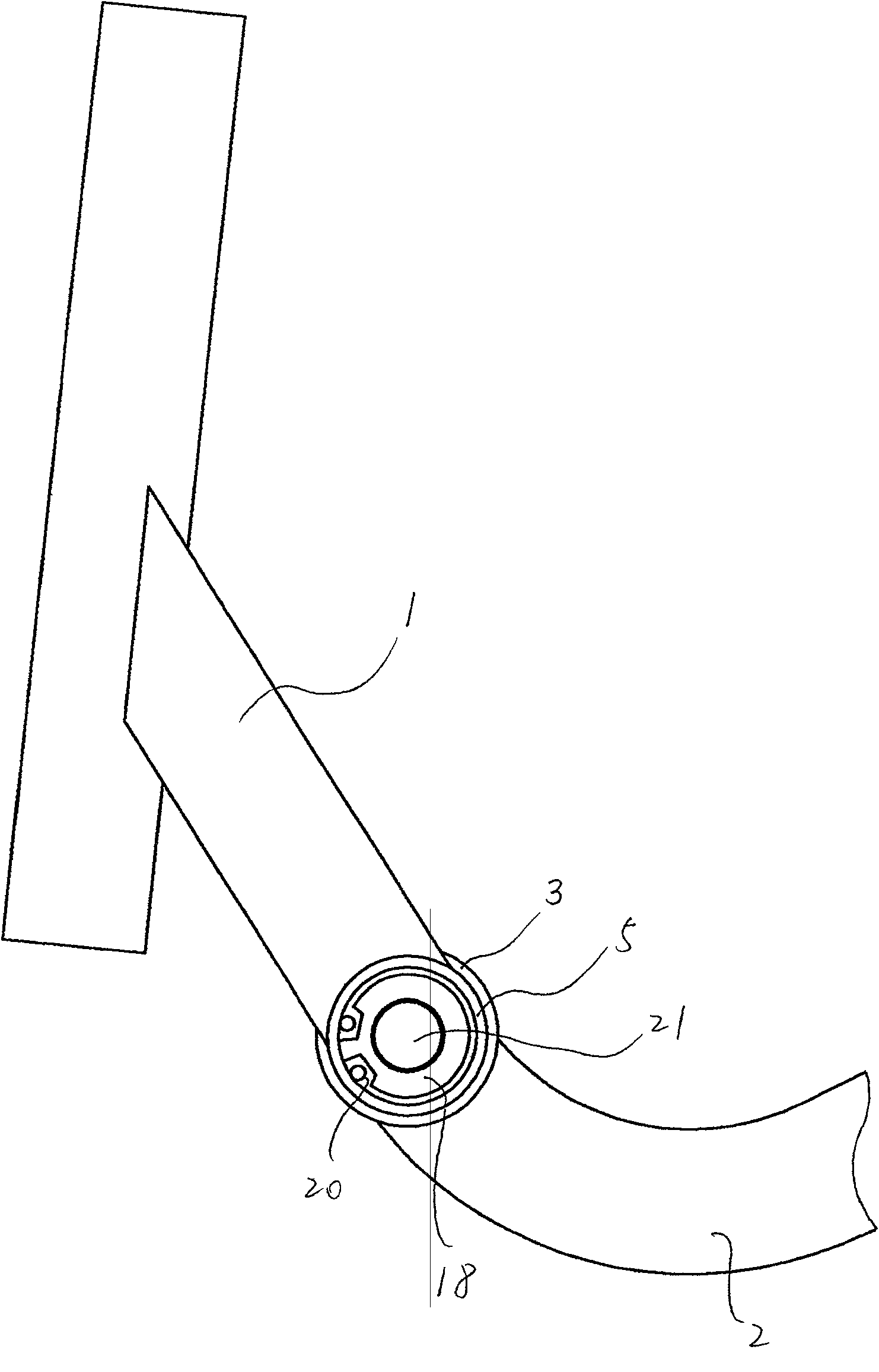
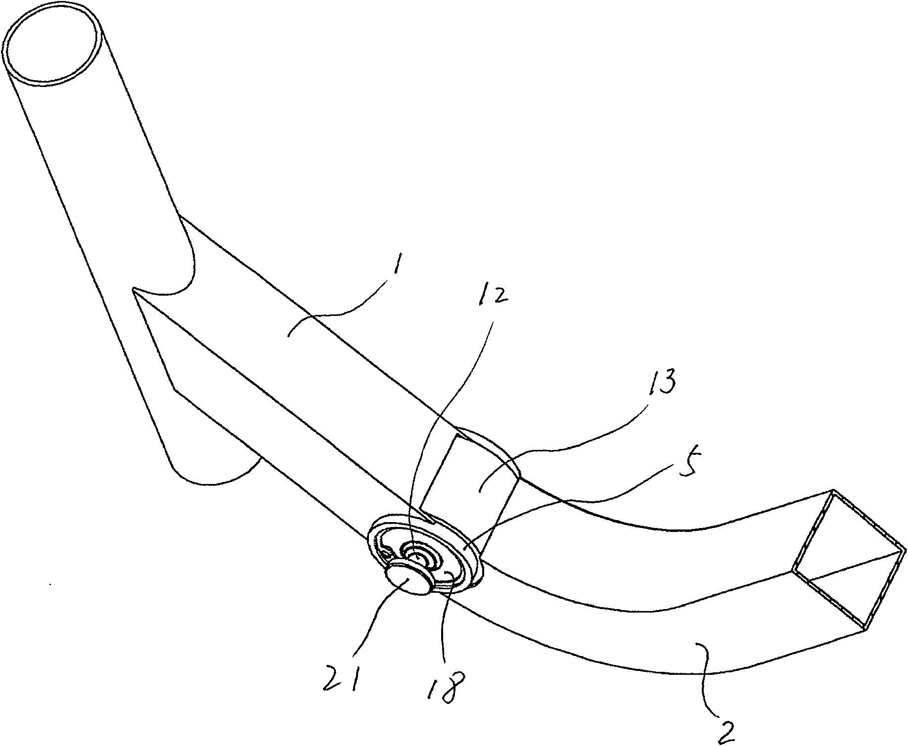
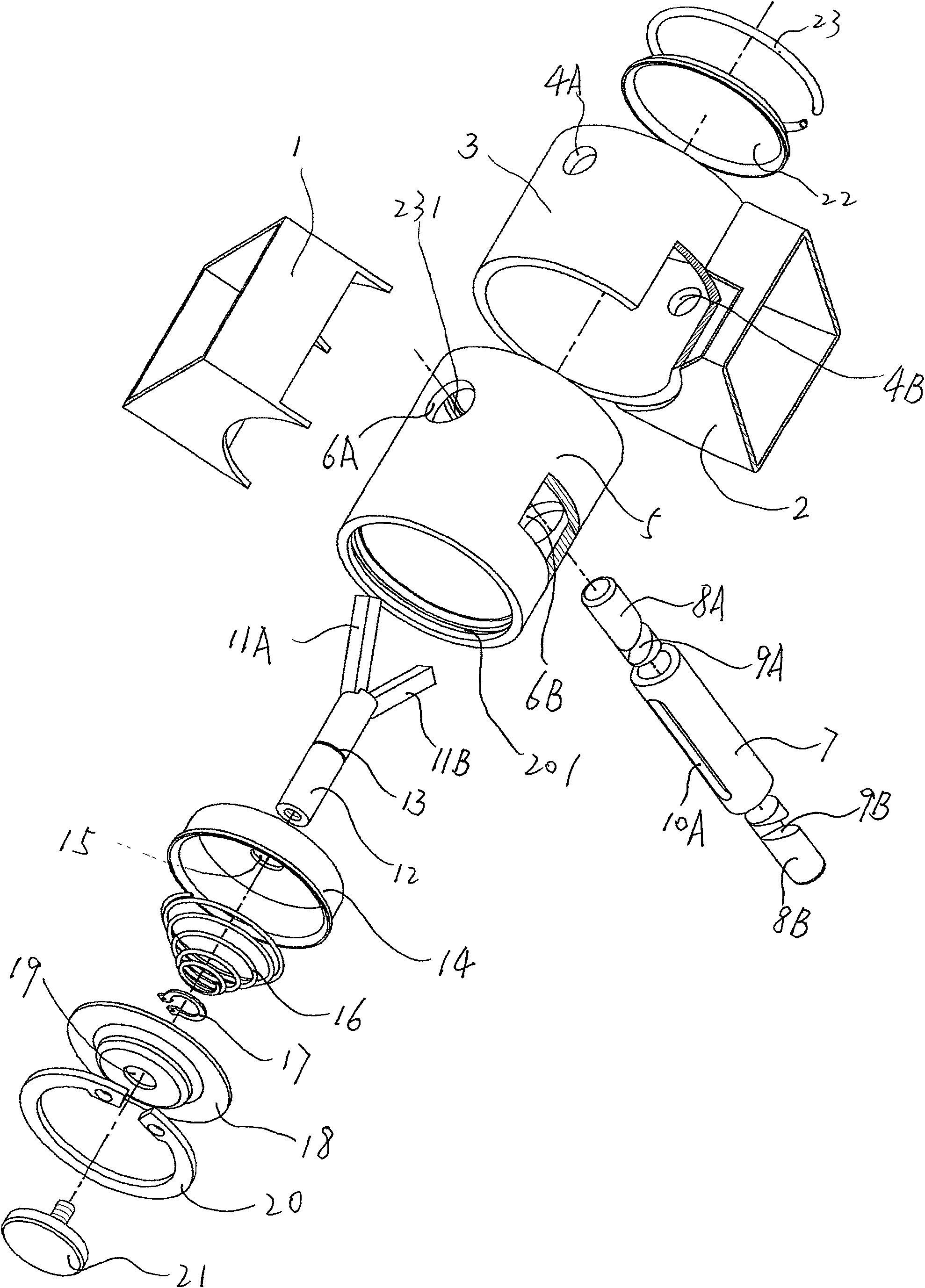
[0021] Such as Figure 1 to Figure 5 As shown, this embodiment describes a folding device in which the pin guide tube is set in the hollow shaft, and the pin hole is set on the hollow shaft sleeve, which includes a front frame 1 and a rear frame 2 In this embodiment, the front frame 1 and the rear frame 2 both refer to a hollow cuboid folding frame, and the front section of the rear frame 2 is an arc-shaped rod.
[0022] The present invention is characterized in that it also includes a hollow shaft sleeve 3 and a hollow shaft 5 that is rotatably fitted in the hollow shaft sleeve 3 and whose two ends extend outside the two ends of the hollow shaft sleeve 3, the outer circumferential surface of the hollow shaft sleeve 3 or the two end and the concave arc welding of the front end of the rear frame 2; And there is a gap between the front frame 1 and the outer peripheral surface of the hollow shaft sleeve 3 . A locking device capable of locking or releasing the relative circumfer...
Embodiment 2
[0030] Such as Figure 7 ~ Figure 11 As shown, what is described in this embodiment is a folding device in which the pin guide tube is set on the hollow shaft sleeve, and the pin hole is set on the hollow shaft. The same thing as Embodiment 1 is that it also includes a front frame 1 , a rear frame 2 , a hollow shaft 5 and a hollow shaft sleeve 3 . The difference from Embodiment 1 is that the folding device in this embodiment is that the front frame 1 is connected to the hollow shaft sleeve 3, the rear frame 2 is connected to both ends of the hollow shaft 5, and the pin guide tube 25 is arranged on the hollow shaft sleeve 3. , The pin hole 24 is located on the hollow shaft 5 .
[0031] see Figure 8 ~ Figure 10 As shown, the hollow shaft 5 can be rotatably fitted in the hollow shaft sleeve 3, and the two ends of the hollow shaft 5 extend outside the two ends of the hollow shaft sleeve 3, and the outer circumferential surface or two ends of the hollow shaft sleeve 3 are in con...
PUM
 Abstract
Description
Claims
Application Information
 - R&D
- Intellectual Property
- Life Sciences
- Materials
- Tech Scout
- Unparalleled Data Quality
- Higher Quality Content
- 60% Fewer Hallucinations
Browse by: Latest US Patents, China's latest patents, Technical Efficacy Thesaurus, Application Domain, Technology Topic, Popular Technical Reports.
© 2025 PatSnap. All rights reserved.Legal|Privacy policy|Modern Slavery Act Transparency Statement|Sitemap|About US| Contact US: help@patsnap.com


