Developing unit for developing static latent image

A developing unit and electrostatic latent image technology, applied to the electric recording process using charge pattern, equipment for electric recording process using charge pattern, and electric recording, which can solve the problem of thinning of toner image

Inactive Publication Date: 2009-10-28
BROTHER KOGYO KK
View PDF7 Cites 0 Cited by
  • Summary
  • Abstract
  • Description
  • Claims
  • Application Information

AI Technical Summary

Problems solved by technology

As a result, the toner image on the paper will also be thinner

Method used


Image

  • Developing unit for developing static latent image
  • Developing unit for developing static latent image
  • Developing unit for developing static latent image

Examples


Embodiment Construction

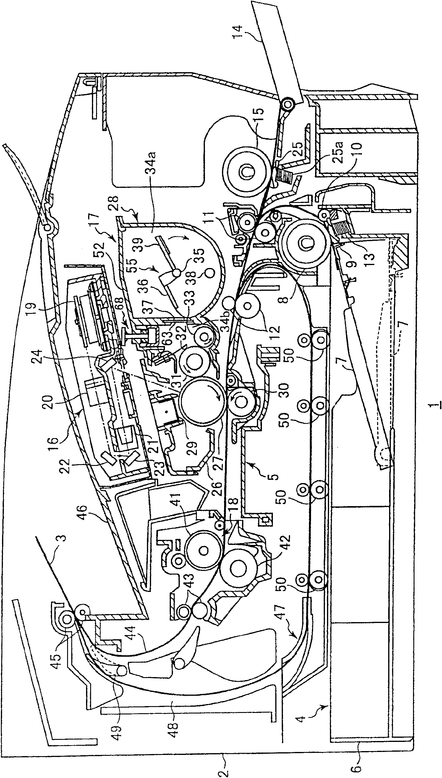
[0027] Next, refer to Figure 2 to Figure 6(b) A laser printer incorporating the developing cartridge according to the first embodiment of the present invention will be described.

[0028] Such as figure 2 As shown, the laser printer 1 includes a main casing 2 , a feeding unit 4 and an imaging unit 5 . The feeding unit 4 and the imaging unit 5 are accommodated in the main housing 2 . The feeding unit 4 feeds the paper 3 to the image forming unit 5 . The image forming unit 5 forms a desired image on the supplied paper 3 .

[0029] The feed unit 4 is located at the lower part of the main casing 2 and includes a paper feed tray 6 , a paper platen 7 , a paper feed roller 8 , a paper feed pad 9 , paper dust removing rollers 10 , 11 and registration rollers 12 . The paper feed tray 6 is detachably attached to the main casing 2 . A paper platen 7 is pivotally and movably provided in the paper feed tray 6 . A paper feed roller 8 and a feed low pad 9 are provided on one end of t...


PUM


Abstract

A developing unit for developing an electrostatic latent image with toner for performing a developing operation. The developing unit includes: a holding chamber wall forming a toner holding chamber; and a developing chamber wall forming a developing chamber in which a developing roller and a toner supply roller are arranged. Inside. A partition wall is provided for separating the holding chamber from the developing chamber. An elongated through hole is formed in the partition wall for fluidly communicating the holding chamber with the developing chamber. A stirring member is rotatably arranged in the holding chamber, and is used for supplying the toner in the holding chamber to the developing chamber through the through hole. A plurality of slats or grids are provided at the through holes so that a plurality of slots are provided between adjacent plates. The slots allow the passage of toner from the holding chamber to the developing chamber, and the slats restrict the return of toner from the developing chamber to the holding chamber.

Description

technical field [0001] The present invention relates to a developing unit for developing an electrostatic latent image. Background technique [0002] figure 1 A developing cartridge 128 for installation in a laser printer is shown. The developing cartridge 128 is divided into a holding chamber 134a for holding toner and a developing chamber 134b for developing an image with the toner. The holding chamber 134a and the developing chamber 13b are in fluid communication with each other through an opening 137 . A stirring member 155 is provided in the holding chamber 134a. Rotation of the agitating member 155 transports the toner held in the holding chamber 134a through the opening 137 to the developing chamber 134b. A supply roller 133 , a developing roller 131 and a layer thickness regulating blade 132 are disposed in the developing chamber 134 b. [0003] When the developing cartridge 128 is properly installed in the laser printer, the developing roller 131 is arranged to...

Claims


Application Information

Patent Timeline
Patent Type & Authority Patents(China)
IPC IPC(8): G03G15/08G03G15/00
CPCG03G15/0877G03G15/0875G03G15/0839
Inventor 佐藤正吾堀乃江满
Owner BROTHER KOGYO KK
Why Eureka
Try Eureka