Quick fixing mechanism of lower roller

A technology of quick installation and rack, applied in the field of quick installation and disassembly mechanism and lower roller quick installation mechanism, which can solve the problems of troublesome disassembly and assembly, difficult positioning of two lower rollers, and high machining accuracy of parts

Inactive Publication Date: 2009-10-28
长治钢铁(集团)锻压机械制造有限公司
View PDF6 Cites 0 Cited by
  • Summary
  • Abstract
  • Description
  • Claims
  • Application Information

AI Technical Summary

Problems solved by technology

The disadvantages brought by this method are: disassembly and assembly are troublesome, each part has high machining accuracy, and the positioning of the two lower rollers is difficult. When debugging the equipment, the two lower rollers are prone to non-parallel and axial movement of the two lower rollers.

Method used


Image

  • Quick fixing mechanism of lower roller
  • Quick fixing mechanism of lower roller
  • Quick fixing mechanism of lower roller

Examples


Embodiment Construction

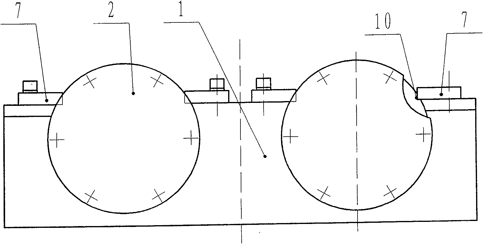
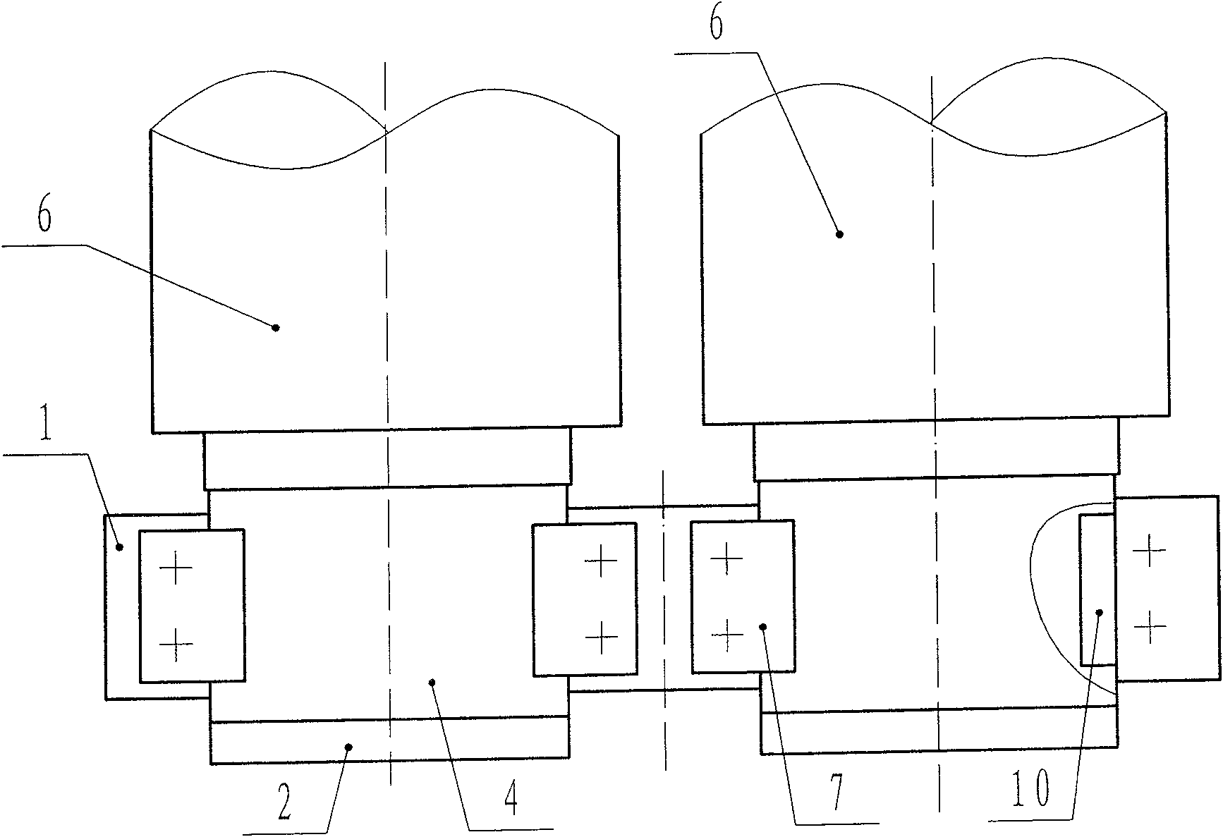
[0015] Such as figure 1 , figure 2 and image 3 Shown: the lower roller quick-installation mechanism, including frame 1, two sets of lower rollers 6, bearings 5, and quick-installation bearing body 4, and a quick-installation bearing body 4 with a U-shaped groove is fixed on the left end of each group of lower rollers 6, The right end of each group of lower rollers 6 is connected with a torsion power device, and the bearing 5 is set on the left shaft head of the lower roller 6, and is located in the U-shaped groove of the quick-installation bearing body 4, and the outer end surface of the quick-installation bearing body 4 is set There is a notch 8, and the quick-loading bearing body 4 is fixed in the corresponding groove 9 of the frame 1 through the notch 8. On the notch 8 of the fast-loading bearing body 4, a positioning step 10 is arranged at the top of the groove 9, and the fast-loading bearing body 4 is fixed by the fixing plate 7 and the positioning step 10 on both sid...


PUM


Abstract

The invention relates to a fast loading and unloading mechanism for the lower roll of a new type of plate rolling machine, which belongs to the technical field of plate rolling machines. The mechanism that can be quickly loaded and unloaded and can solve the positioning problem of the lower roller adopts the following technical scheme: the left end of the lower roller is fixed with a quick-install bearing body with a U-shaped groove, the bearing is set on the left shaft head of the lower roller, and is located on the quick-install bearing In the U-shaped groove of the body, there is a notch on the outer end surface of the quick-installation bearing body, and the quick-installation bearing body is fixed in the corresponding groove of the frame through the notch; the invention can be widely applied to plate rolling machines.

Description

technical field [0001] The invention relates to a quick loading and unloading mechanism for a lower roll, which relates to a new quick loading and unloading mechanism for a lower roll of a plate rolling machine, and belongs to the technical field of plate rolling machines. Background technique [0002] At present, the assembly of the lower roll of the plate rolling machine adopts the form of split assembly, that is, the bearing, cover, spacer, bearing body, frame and other parts are assembled together in a fixed order. The disadvantages brought by this method are: disassembly and assembly are troublesome, each part has high processing precision, and the positioning of the two lower rollers is difficult. When debugging the equipment, the two lower rollers are prone to non-parallel and axial movement of the two lower rollers. Contents of the invention [0003] The present invention overcomes the problems existing in the prior art, and the problem to be solved is: to provide ...

Claims


Application Information

Patent Timeline
Patent Type & Authority Patents(China)
IPC IPC(8): B21D5/14
Inventor 邢伟荣李建英郭永平孙卫强
Owner 长治钢铁(集团)锻压机械制造有限公司
Why Eureka
Try Eureka