
An electrostatic precipitator

A technology of electrostatic precipitation and precipitator, applied in the direction of external electrostatic separator, electrostatic separation, electrode structure, etc., can solve the problems of uneven charging degree, unable to overcome the pinning effect and particle injection, and achieve the effect of low operating power

Inactive Publication Date: 2009-10-28
THE SEC OF STATE FOR DEFENCE IN HER BRITANNIC MAJESTYS GOVERNMENT OF THE UK OF GREAT BRITAIN & NORTHERN IRELAND
View PDF6 Cites 0 Cited by
  • Summary
  • Abstract
  • Description
  • Claims
  • Application Information

AI Technical Summary

Problems solved by technology

[0007] However, this setup is unsatisfactory in that, even when the particle size is increased by coagulation, the degree of charging produced on the particles at the desired air flow is not uniform
In addition, the strength of the concentration field acting on the particles at the desired operating voltage and air flow rate often or cannot overcome the pinning effect or prevent the particles from being ejected from the charging field

Method used


Image

  • An electrostatic precipitator
  • An electrostatic precipitator
  • An electrostatic precipitator

Examples


Embodiment Construction

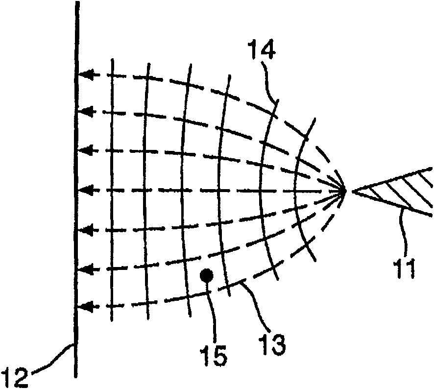
[0040] see now figure 1 , the electrostatic field generated between the point electrode 11 and the planar electrode 12 to which a high voltage is applied has field lines 13 (dotted lines) that diverge outward from the point electrode 11 . The ions and particles 15 charged in the field are transported towards the planar electrode 12 along the electric field lines 13 by the potential gradient represented by the progress from the equipotential lines 14 (all) of the point electrodes 11 .

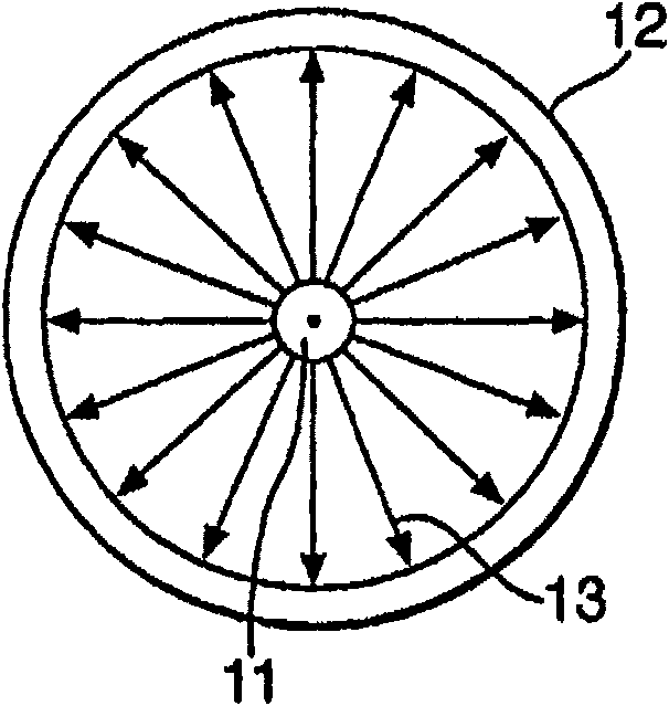
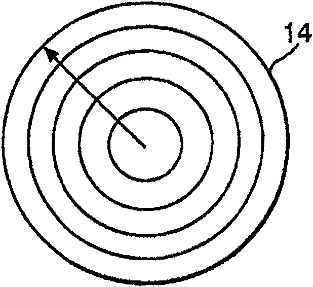
[0041] Figure 2a and 2b The electric field lines 13 and the equipotential lines 14 that arise when the planar electrode 12 is formed as a cylindrical electrode and the point electrode 11 is mounted coaxially thereto are shown. This structure, which forms the basis of several prior art precipitators, generates an electrostatic field in which the electric field lines diverge radially from the point electrodes 11 . This electrostatic field is associated with a potential gradient which causes io...


PUM


Abstract

An electrostatic precipitator is disclosed. The precipitator includes a conduit for flowing particles in the air flow, a device for generating an electrostatic field generally perpendicular to the air flow, and an ion supply capable of charging the particles, wherein the generating device includes a point electrode and two A three-dimensional planar electrode, characterized in that the planar electrode includes an ion source, the point electrode includes a counter electrode, and the counter electrode is grounded.

Description

technical field [0001] The invention relates to an electrostatic precipitator. The present invention relates particularly, but not exclusively, to an electrostatic precipitator suitable for collecting and analyzing airborne particles including microorganisms in the environment. Background technique [0002] Analysis of airborne particles in the environment often requires sampling large volumes of air. Current collection techniques often rely on accelerating the air to very high velocities to exploit the differential momentum between the particles and the air to cause the particles to hit the collection surface or liquid. However, such impaction techniques typically require very high energy input, and their capabilities are limited to separating small particles (under 1 μm). [0003] The aggregation of particles at the surface of electrodes in an electrostatic field is a well known phenomenon which is exploited by electrostatic precipitators to separate dust and smoke parti...

Claims


Application Information

Patent Timeline
Patent Type & Authority Patents(China)
IPC IPC(8): B03C3/45B03C3/41B03C3/06
CPCB03C3/45B03C3/41B03C3/06Y10S55/38
Inventor 詹姆斯·麦克唐纳·克拉克蒂莫西·格雷厄姆·福特莫里斯·达韦莱尔·沃克斯蒂芬·雷·普雷斯顿
Owner THE SEC OF STATE FOR DEFENCE IN HER BRITANNIC MAJESTYS GOVERNMENT OF THE UK OF GREAT BRITAIN & NORTHERN IRELAND
Learn More