Flat resolution correcting method for image optical system and apparatus thereof

A technology of planar resolution and optical system, which is applied in the parts of TV system, image communication, TV, etc., can solve the problems affecting the accuracy and speed of correction, linear error, and the increase of the complexity of optical system mechanism, etc.

Inactive Publication Date: 2009-10-21
CHROMA ATE
View PDF3 Cites 0 Cited by
  • Summary
  • Abstract
  • Description
  • Claims
  • Application Information

AI Technical Summary

Problems solved by technology

However, in this type of technology, the scale must be set so that its horizontal axis is parallel to the horizontal axis determined by the pixels of the image capture device. If there is an inclination during the setting, the measurement result will be higher than the actual measurement result. object size is short, resulting in linearity error
As a result, the scale used in the conventional image optical system plane resolution calibration method must be equipped with a rotating platform to adjust the level of the scale, which increases the complexity of the optical system mechanism and also affects the accuracy and speed of calibration.

Method used


Image

  • Flat resolution correcting method for image optical system and apparatus thereof
  • Flat resolution correcting method for image optical system and apparatus thereof
  • Flat resolution correcting method for image optical system and apparatus thereof

Examples


Embodiment Construction

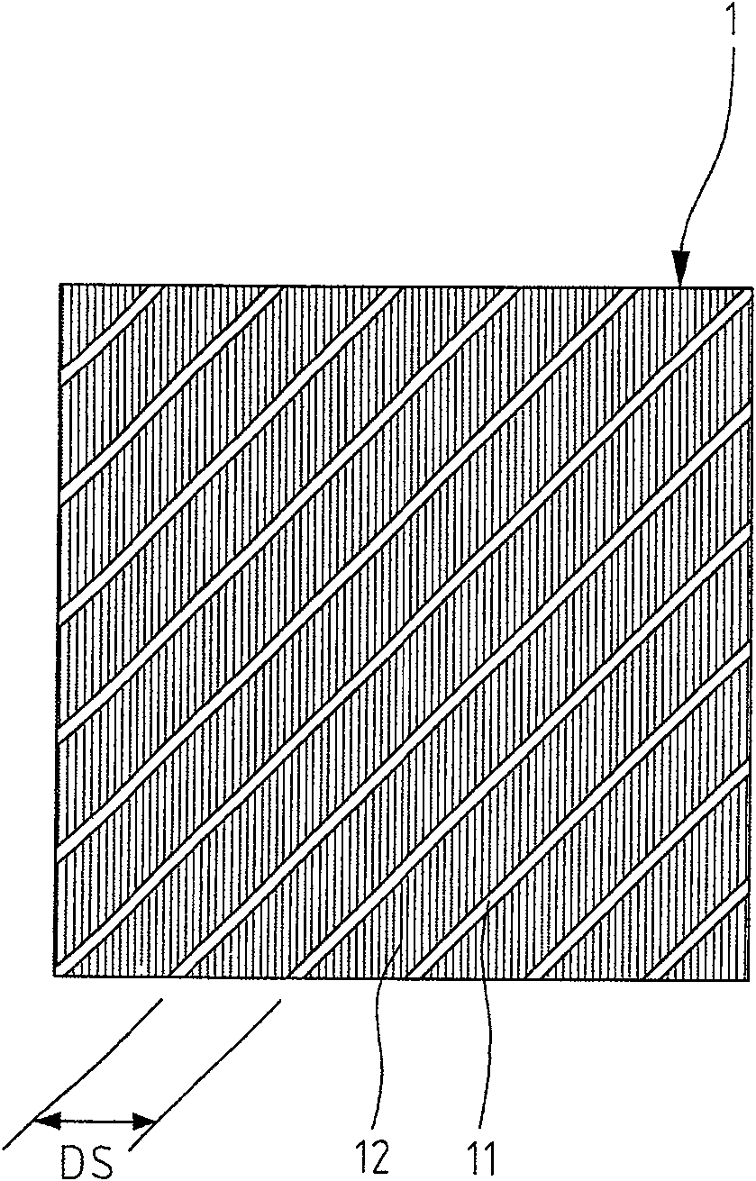
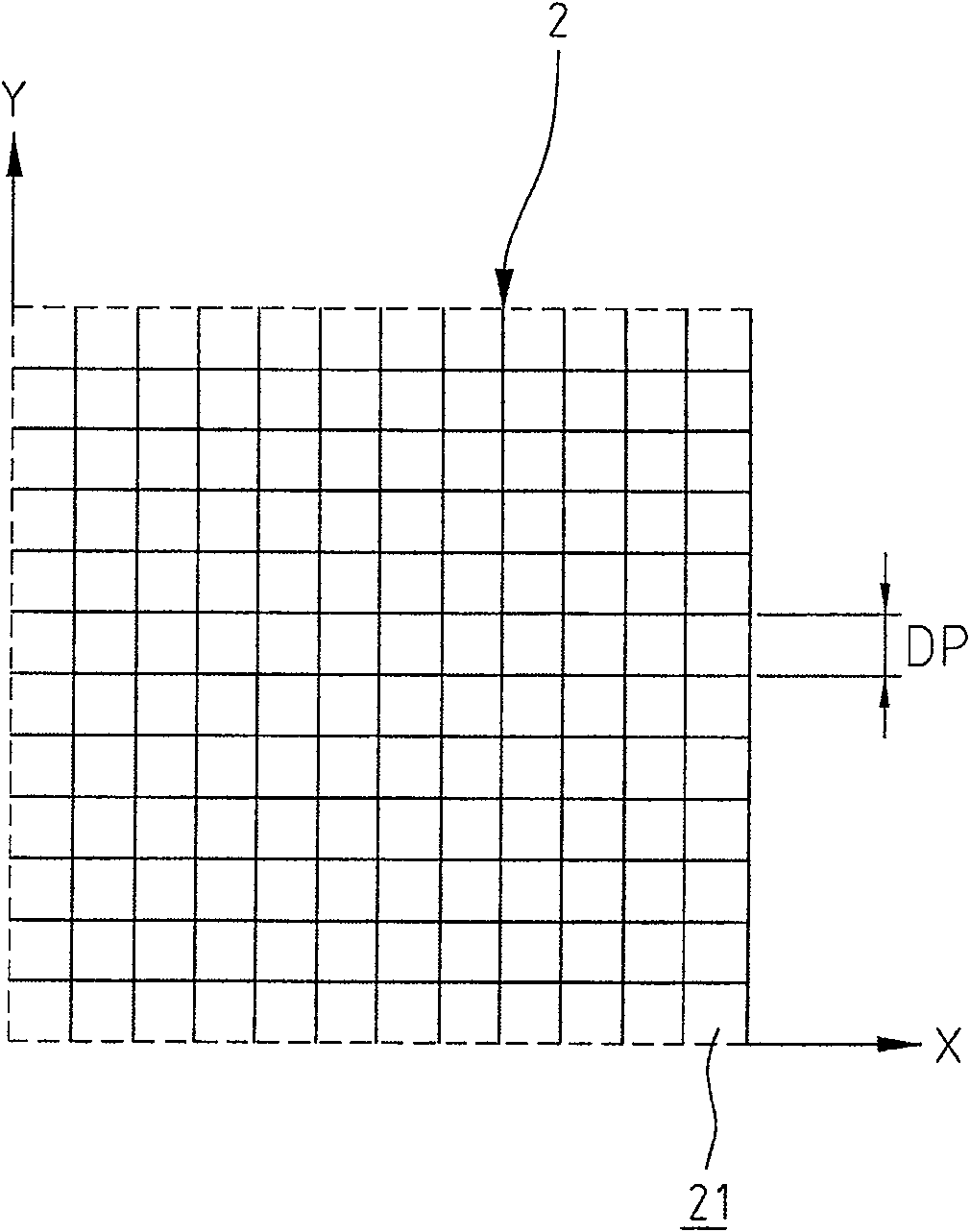
[0029] figure 1 It is a schematic diagram showing the calibration samples used in the plane resolution calibration method of the imaging optical system of the present invention; figure 2 It is a schematic diagram showing the coordinates of the sensing component of the method for correcting the planar resolution of the image optical system of the present invention. refer to figure 1 As shown, it is the calibration sample 1 used in the present invention. The calibration sample 1 has several bright lines 11 and dark lines 12 alternate stripes, and the bright lines 11 are parallel to each other and have the same width, and the dark lines 12 are also parallel to each other. and have the same width, wherein the actual distance between the bright lines 11 is denoted as DS. Also, refer to figure 2 As shown, it is a schematic diagram of the measurement coordinates 2 not shown in the figure of the image sensing device used in the present invention, wherein each unit cell 21 corre...


PUM


Abstract

The invention relates to a plane resolution correction method and device of an image optical system, comprising a correction sample and an image sensing device, the surface of the correction sample has straight lines alternated with bright lines and dark lines, and the correction sample is set on a plane to be measured Here, an image sensing device has image capturing means, memory means and logic calculation means. In order to execute the image information of the calibration sample and store the image information, select and calculate the straight line equation of the bright line stripes, through the straight line slope and intercept of the straight line equation, and use the intercept to calculate the average distance between adjacent bright lines, and finally use geometric mathematics The method calculates the magnification of the image captured by the image sensing device.

Description

technical field [0001] The present invention relates to a plane resolution calibration method of an image optical system and its device, and in particular provides a calibration method for an image capture device, which is used to correct the image magnification corresponding to the pixels. Background technique [0002] The known planar resolution calibration method of an image optical system provides calibration for an image capture device to determine the image magnification corresponding to the pixels of a CCD sensor or a CMOS sensor. Usually this kind of technology is to capture the image of the scale scale marked with the size through the image capture device, refer to Figure 7 As shown, the two scale line positions P1 and P2 are selected by image processing or manually, and the pixel distance between them is calculated, and the actual distance between P1 and P2 on the scale 6 is determined by design. By comparing the actual distance size with the pixel distance, the a...

Claims


Application Information

Patent Timeline
Patent Type & Authority Patents(China)
IPC IPC(8): H04N17/00H04N5/14
Inventor 林耀明张维哲张宏彰
Owner CHROMA ATE
Why Eureka
Try Eureka