
Roller chain for driving

A technology of roller chains and inner chain links, applied in the direction of transmission chains, etc., can solve the problems of not providing light weight, and achieve the effect of large weight reduction and avoiding stress concentration

Inactive Publication Date: 2009-10-14
HONDA MOTOR CO LTD
View PDF7 Cites 0 Cited by
  • Summary
  • Abstract
  • Description
  • Claims
  • Application Information

AI Technical Summary

Problems solved by technology

However, the shape of the guide link plate is only determined so that the amount of deformation is the same as that of the link plate, and it does not provide a shape that satisfies maintenance of strength, suppresses deformation due to load, and achieves weight reduction.
In addition, there has been no active research on reducing the weight of link plates. For example, in the development of driving roller chains mounted on vehicles for power transmission, weight reduction without reducing strength has become an important issue.

Method used


Image

  • Roller chain for driving
  • Roller chain for driving
  • Roller chain for driving

Examples


Embodiment Construction

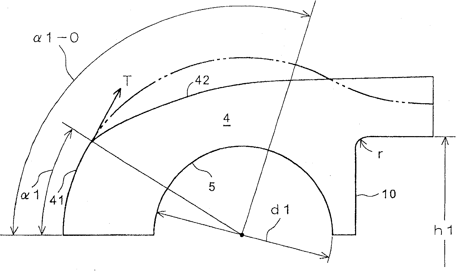
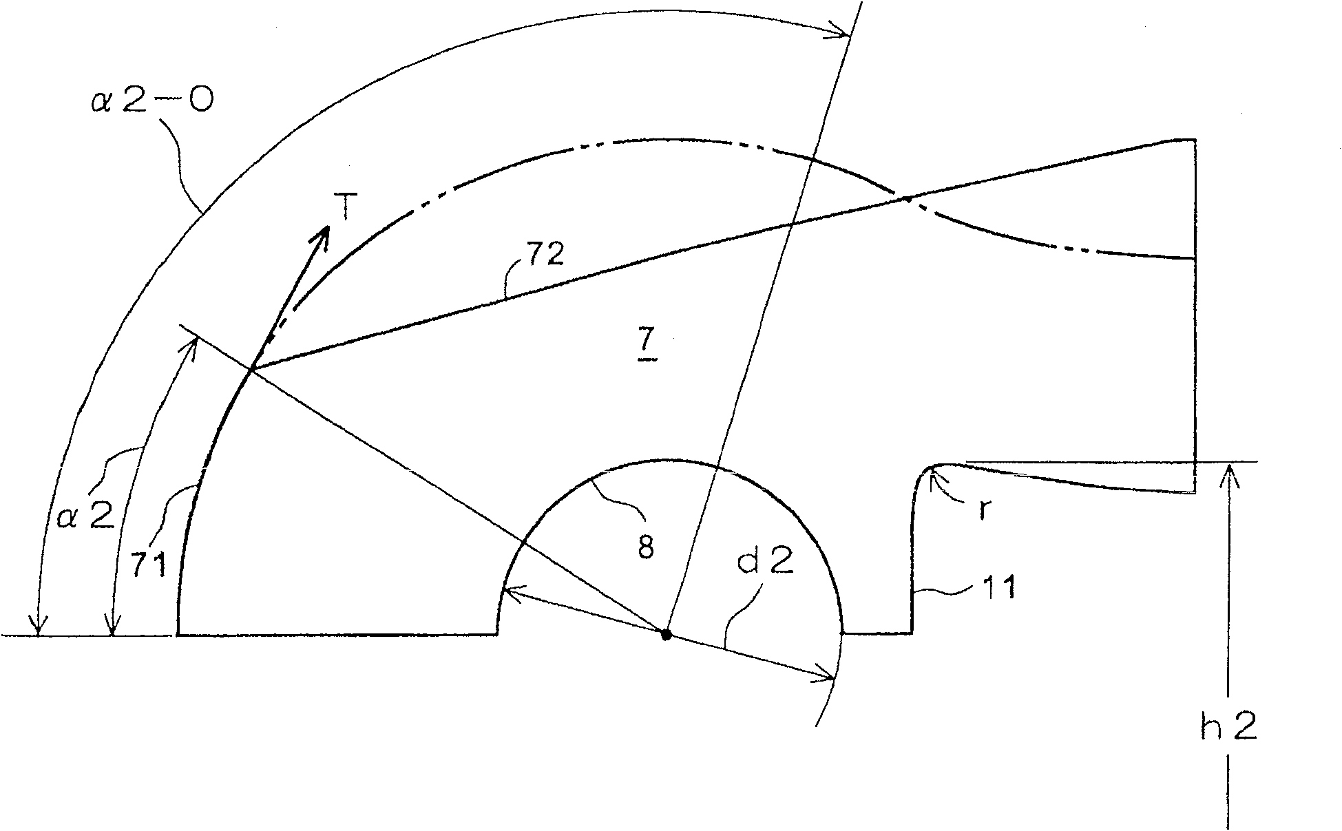
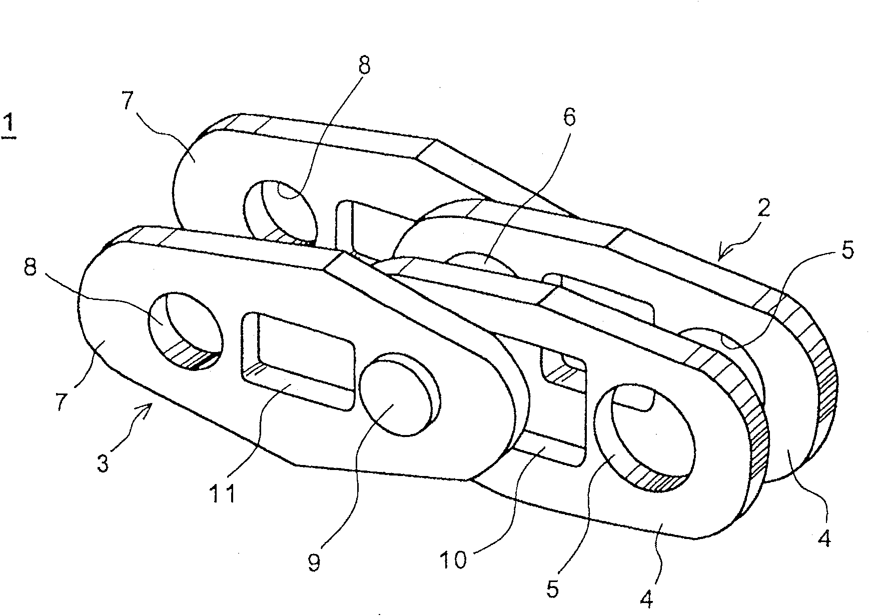
[0031] Hereinafter, one embodiment of the present invention will be described with reference to the drawings. image 3 It is a perspective view of main parts of a driving roller chain according to an embodiment of the present invention, Figure 4 is its top view. This driving roller chain is used, for example, in motorcycles to transmit the output power of an engine to drive wheels. The inner link 2 and the outer link 3 are sequentially connected to form a drive roller chain 1 of a desired length. The inner link 2 is composed of a pair of inner link plates (hereinafter simply referred to as “inner plates”) 4 and a bushing 6 fitted into a bushing hole 5 formed in the inner plates 4 . On the other hand, the outer link 3 is composed of a pair of outer link plates (hereinafter simply referred to as “outer plates”) 7 and coupling pins 9 fitted into pin holes 8 formed in the outer plates 7 .

[0032] In addition to two pairs of bushing holes 5 , the inner plate 4 also has a recta...


PUM


Abstract

The present invention provides a lightweight driving roller chain that optimizes the shape of the link plates and minimizes the weight. The outer plate (7) has an outer window (11) formed between a pair of coupling pin holes (8); the inner plate (4) has an inner window (10) formed between a pair of bushing holes (5). The corners of the outer and inner windows are rounded. The profile of the outer plate (7) and the inner plate (4) consists of arc portions (41), (71) at both ends of the length direction, and from the arc portions (41), (71) towards the center of the length direction, And the substantially straight sides (42), (72) are formed toward the width direction outer side of this outer plate and inner plate. The side (72) is set so that the tangential direction of the end of the arc portion (71) of the outer plate (7) faces inward.

Description

technical field [0001] The present invention relates to a driving roller chain, and particularly relates to a driving roller chain suitable for realizing weight reduction. Background technique [0002] Japanese Patent Application Laid-Open No. 2006-064049 discloses a roller chain having a link plate whose outer shape from the pin hole of the link pin to the front end side is such that, viewed from the center of the pin hole, Consistently smooth bulges in the greatest way at 45° from the centerline. Using the link plate of the roller chain can reduce the increase in weight and increase the strength of the roller chain. [0003] In addition, Japanese Patent Application Laid-Open No. 4-210144 discloses a silent chain guide link plate that can reduce the stress on the coupling pin by making the deformation amount according to the load the same as that of the link plate. On the guide link plate, openings or slits are formed in addition to pin holes through which coupling pins p...

Claims


Application Information

Patent Timeline
Patent Type & Authority Patents(China)
IPC IPC(8): F16G13/06
CPCF16G13/06
Inventor 本间秀树前田和寿佐佐木畅伊藤未丈
Owner HONDA MOTOR CO LTD
Learn More