Sliding-raising mechanism of ditcher
A ditching machine, sliding warping technology, applied in the direction of excavation/covering ditches, application, planting methods, etc., can solve the problems of flameout, diesel engine speed reduction, insufficient tightening force, etc., to achieve high soil moisture and low cutting resistance , the effect of low soil firmness
- Summary
- Abstract
- Description
- Claims
- Application Information
AI Technical Summary
Problems solved by technology
Method used
Image
Examples
Embodiment 1
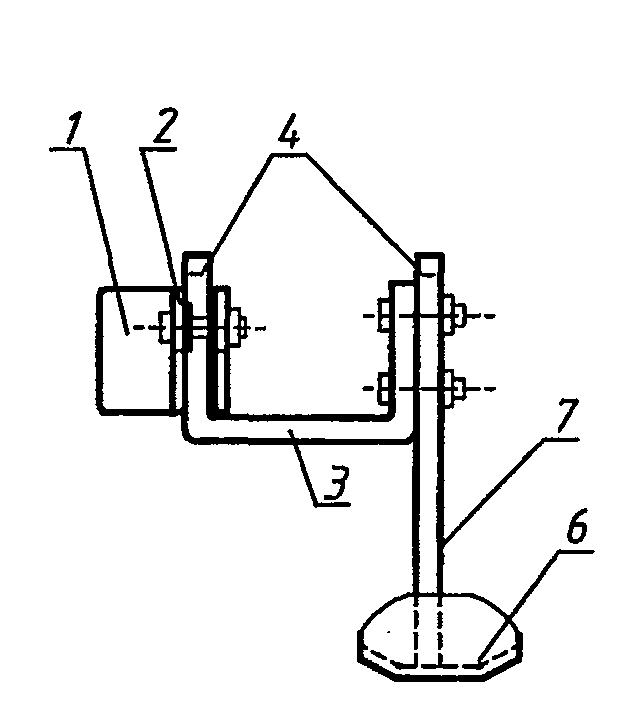
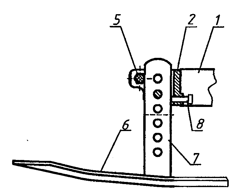
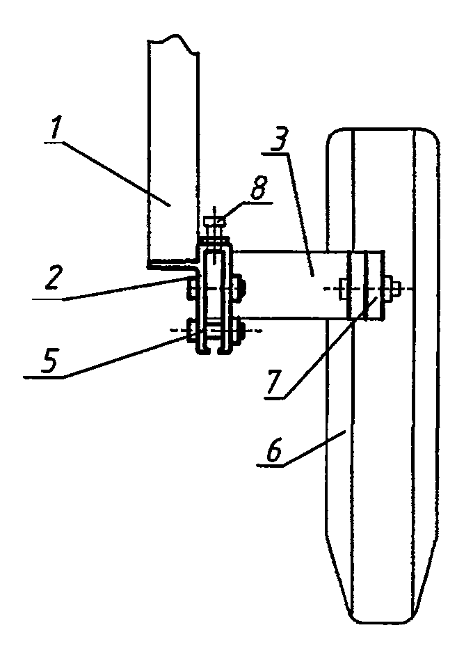
[0017] Embodiment 1. The sliding and warping mechanism of the ditching machine includes a closed casing arranged on the front end of the ditching machine frame arm 1 and a sliding and warping 6. One side of the closed casing is provided with a bolt hole and a sliding and warping post 7 is provided with a plurality of bolt holes. In addition, a U-shaped joint block 3 is provided, and the two vertical columns of the U-shaped joint block are provided with bolt holes; when a new ditch is opened in ordinary flat fields, the bolts are used to directly fix the sliding warped column on the closed casing , When it is necessary to repeat ditching to the old ditch, the U-shaped joint block is first fixed on the closed casing with bolts, and then the sliding upright column is bolted on another vertical column of the U-shaped joint block.
Embodiment 2
[0018] Embodiment 2, as figure 1 , 2 , 3 shown. The sliding mechanism of the ditching machine includes the sliding clip 2 and the sliding clip 6 arranged at the front end of the ditching machine frame arm 1; the front end of the sliding clip 2 is an opening, and the middle parts of both sides are symmetrically provided with bolt holes; the sliding clip Column 7 is provided with a plurality of bolt holes. Also be provided with a U-shaped connecting block 3 in addition, two vertical columns 4 of the U-shaped connecting block are provided with bolt holes; , When it is necessary to repeat the ditching of the old ditch, the U-shaped joint block is first fixed on the sliding clamp with bolts, and then the sliding vertical column is fixed on another vertical column of the U-shaped joint block with bolts. like Figure 4 and Figure 5 As shown, clamping bolt holes 5 are arranged symmetrically on the front of both sides of the sliding clip, and the two sides of the sliding clip 2 c...
PUM
 Abstract
Description
Claims
Application Information
 - Generate Ideas
- Intellectual Property
- Life Sciences
- Materials
- Tech Scout
- Unparalleled Data Quality
- Higher Quality Content
- 60% Fewer Hallucinations
Browse by: Latest US Patents, China's latest patents, Technical Efficacy Thesaurus, Application Domain, Technology Topic, Popular Technical Reports.
© 2025 PatSnap. All rights reserved.Legal|Privacy policy|Modern Slavery Act Transparency Statement|Sitemap|About US| Contact US: help@patsnap.com


