Three level electric jar for bearing ball silk bar

A technology of ball screw and electric cylinder, which is applied in the direction of electric components, electrical components, electromechanical devices, etc., can solve the problems of electric cylinder design inconvenience, self-locking, and small installation size, so as to save axial installation space and improve work efficiency. Efficiency, the effect of preventing backlash under pressure

Inactive Publication Date: 2009-09-16
ZHEJIANG UNIV
View PDF6 Cites 1 Cited by
  • Summary
  • Abstract
  • Description
  • Claims
  • Application Information

AI Technical Summary

Problems solved by technology

[0002] At present, single-stage electric cylinders have been widely used at home and abroad, but because they only have a single-stage transmission mechanism, the working stroke is limited by the size of the cylinder itself, and the length of the push rod and the installation size of the cylinder body must be increased in exchange for a large working stroke. The cylinder is very heavy and cannot be used in occasions that require a small installation size but a large working stroke; there are also multi-stage hydraulic cylinders in the hydraulic system, but the hydraulic cylinder itself needs to provide oil source and corresponding hydraulic equipment, which is not convenient to use; In terms of the realization technology of electric cylinders, there are usually two types of screw screw transmission and ball screw transmission. The screw screw has low efficiency and high heat generation, while the ball screw has high efficiency, but due to its disadvantage of not being self-locking, it is difficult for The design of the electric cylinder is inconvenient

Method used


Image

  • Three level electric jar for bearing ball silk bar
  • Three level electric jar for bearing ball silk bar
  • Three level electric jar for bearing ball silk bar

Examples


Embodiment Construction

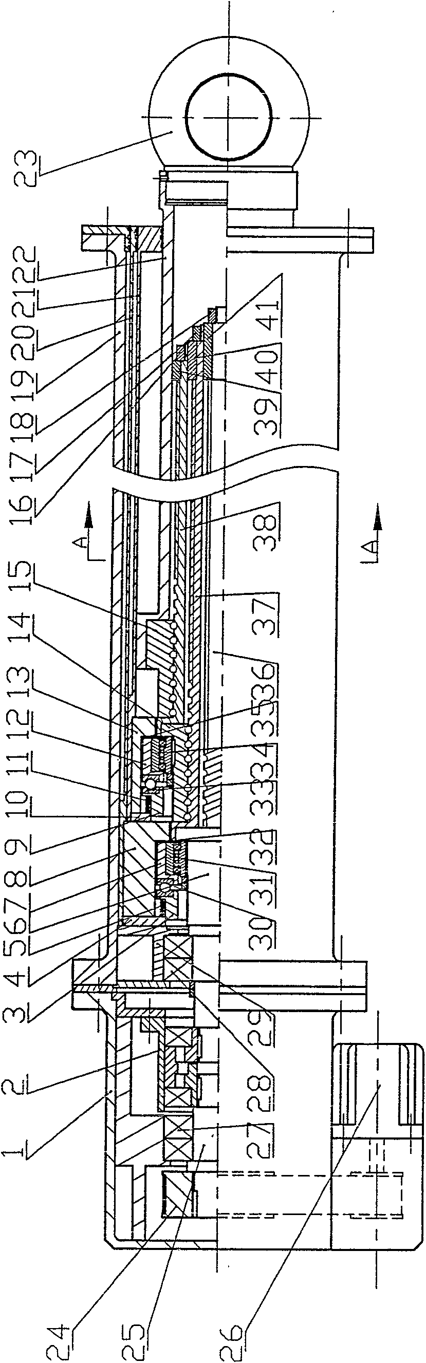
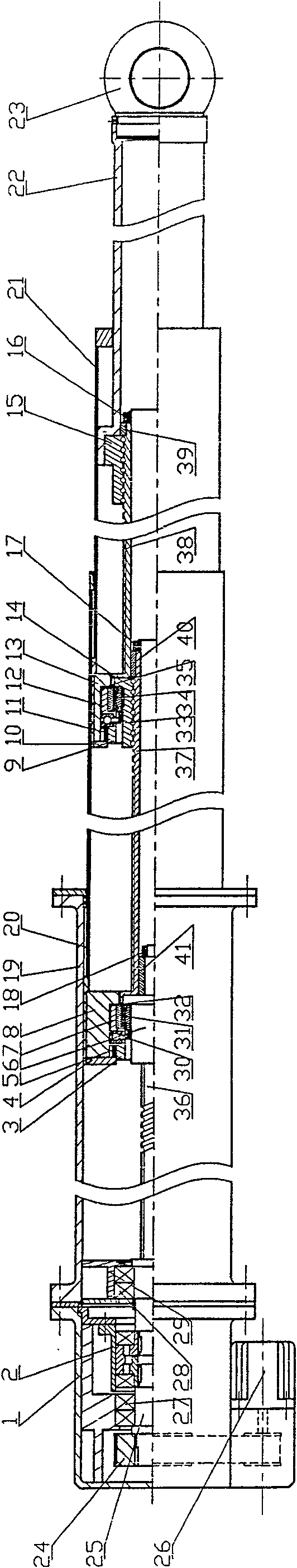
[0013] The present invention will be further described below in conjunction with the accompanying drawings and embodiments.

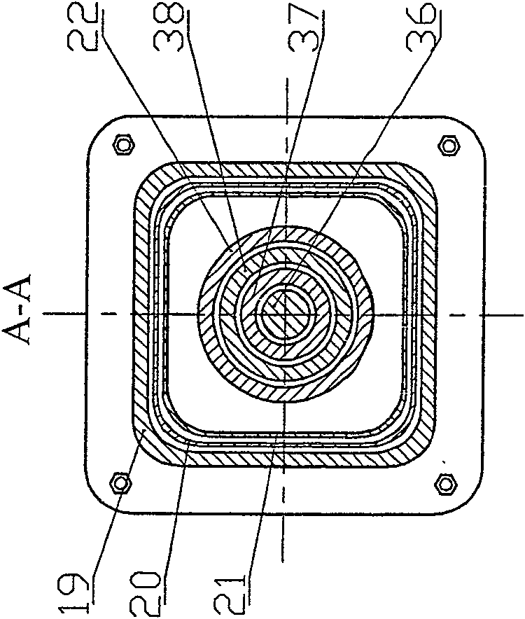
[0014] Such as figure 1 , figure 2 , image 3 As shown, the present invention includes installing the first-stage nut 6 on the helical groove of the first-stage screw mandrel 36, and the end of the first-stage screw mandrel 36 is equipped with a shaft-end stopper 41, and is fastened by the shaft-end nut 18. The inner ring of the overrunning clutch 31 is fixed on the first stage nut 6, the outer ring of the one-way overrunning clutch 31 is fixed with the sleeve 7, and the thrust ball bearing 30 is installed on the sleeve 7, and the other side of the thrust ball bearing 30 is installed On the slider 3, the slider 3 is covered with a spring 5, the spring 5 is pressed by the slider 3 and the cylinder stopper 4, and the cylinder stopper 4 and the middle block 8 are fixedly installed on the first-stage inner cylinder 20 , the sleeve 7 and the middle block...


PUM


Abstract

The invention discloses a third-level ball screw electric cylinder. A servo motor drives a first-level screw to rotate through a bidirectional overrunning clutch; a first-level nut is connected with a first-level internal cylinder through a self-locking mechanism with a one-way overrunning clutch; meanwhile, a second-level hollow screw is fixedly connected with a first-level nut. A second-level nut is connected with a second-level internal cylinder through the self-locking mechanism with the one-way overrunning clutch; meanwhile, a third-level hollow screw is fixedly connected with the second-level nut. A third-level nut is fixedly connected with a push rod; the other end of the push rod is connected with an earring. The three-level screws are capable of rotating by extending outwards one by one to push their own nuts to move in parallel. The three-level screws are sleeved together in overlapping, thus saving the axis direction room and capable of being applied in the working occasion with limited installation room. The ball screw is able to reduce the friction, and decrease calorific value, thus greatly improving the working efficiency. Meanwhile, the ball screw adopts the self-locking mechanism to prevent the backspace from being pressed.

Description

technical field [0001] The invention relates to an electric cylinder, in particular to a three-stage ball screw electric cylinder. Background technique [0002] At present, single-stage electric cylinders have been widely used at home and abroad, but because they only have a single-stage transmission mechanism, the working stroke is limited by the size of the cylinder itself, and the length of the push rod and the installation size of the cylinder body must be increased in exchange for a large working stroke. The cylinder is very heavy and cannot be used in occasions that require a small installation size but a large working stroke; there are also multi-stage hydraulic cylinders in the hydraulic system, but the hydraulic cylinder itself needs to provide oil source and corresponding hydraulic equipment, which is not convenient to use; In terms of the realization technology of electric cylinders, there are usually two types of screw screw transmission and ball screw transmissi...

Claims


Application Information

Patent Timeline
Patent Type & Authority Patents(China)
IPC IPC(8): H02K7/06F16H25/12
Inventor 王宣银赵雁斌
Owner ZHEJIANG UNIV
Why Eureka
Try Eureka