
Connector and connector device

A connector and mating connector technology, which is applied to the parts of the connection device, the device to prevent wrong connection, the connection and other directions to achieve the effect of reducing the operating load

Inactive Publication Date: 2009-09-16
SUMITOMO WIRING SYST LTD
View PDF5 Cites 0 Cited by
  • Summary
  • Abstract
  • Description
  • Claims
  • Application Information

AI Technical Summary

Problems solved by technology

[0005] However, since unlocking is affected by forcibly elastically deforming the locking arm after the male and female housings are separated for maintenance or the like, an additional operating force is required to unlock if the two locking surfaces form a vertical plane, which becomes For operating load reasons

Method used


Image

  • Connector and connector device
  • Connector and connector device
  • Connector and connector device

Examples


no. 1 example

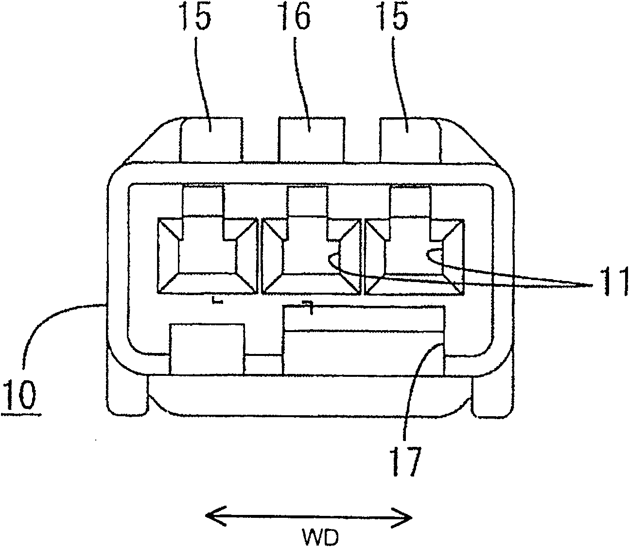
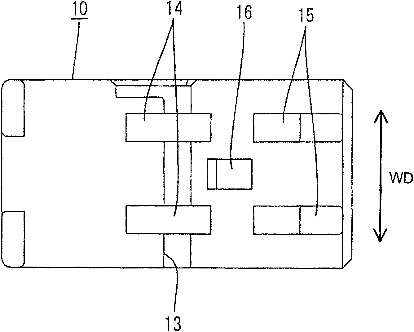
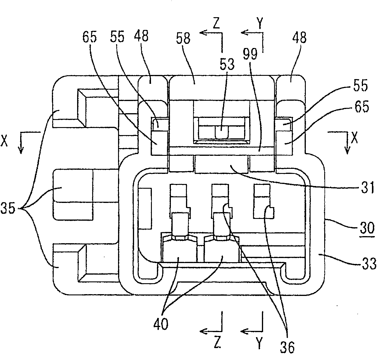
[0072] Refer to attached Figures 1 to 18 A first embodiment of the present invention will be described. In this embodiment, the slider (as the preferred movable member) 50 and at least one compression coil spring (corresponding to the preferred biasing means) will be at least partially fitted to the male connector housing (hereinafter, simply referred to as "male housing 30"), the male housing can be connected to a female connector housing (hereinafter, only referred to as "female housing 10"). In the following description, the sides where the male housing 30 and the female housing 10 are connected are referred to as fronts in the forward and rearward directions.

[0073] The female housing 10 is made of, for example, a synthetic resin material, and is preferably substantially in the form of a monolithic block, and one or more such as three cavities 11 are preferably arranged substantially side by side in one or more of the female housing 10 One or more corresponding female...

no. 2 example

[0106] attached Figure 19 A second embodiment of the present law is shown. This second embodiment differs from the first embodiment in the structure of the lock arm 31 and the arm pressing portion 52, but is similar or substantially the same in other structures.

[0107] The locking arm 31 of the second embodiment includes an arm main body 45 in the form of a long and narrow rod, and a substantially block-shaped locking portion 39 is continuous with the leading end of this arm main body 45 . The width of locking portion 39 is preferably greater than the width of arm main body 45, and rear surface 39A of locking portion 39 is a stepped surface, and this stepped surface is at an angle not equal to 0° or 180°, preferably substantially opposite to arm main body 45. The side surfaces are at right angles. On the other hand, an arm exit portion 57 for at least partially accommodating the lock arm 31 is formed at the guide side of the arm pressing portion 52 so as to have openings ...


PUM


Abstract

The object of the invention is to enable simple release of the locking while ensuring sufficient holding force of the two shells already correctly connected to each other. The slider 50 and the compression coil spring 70 are assembled in the male housing 30, and the slider can move along the forward and backward directions, and the compression coil spring is used to receive the female housing 10 as the slider 50 is connected. Pushing and moving backward builds up biasing force. The male housing 30 is also provided with a cantilever-shaped and elastically deformable locking arm 31 extending in the forward and rearward directions, and the female housing 10 is provided with an engaging portion 16 which can be engaged with the locking arm. The locking portion 39 is elastically engaged. The slider 50 includes an unlocking portion 99 for engaging with the locking portion 39 that has been engaged with the engagement portion 16 as the slider 50 moves backward, thereby disengaging the locking arm 31 from the engagement portion 16. The locking arm 31 is elastically deformed.

Description

technical field [0001] The present invention relates to a connector and a connector device provided with a partial connection preventing function. Background technique [0002] A connector provided with a partial connection preventing function is disclosed in Japanese Unexamined Patent Application No. 2004-134259. The connector consists of a male housing and a female housing, the male housing is formed with a receptacle into which the female housing is fittable, wherein a slider movable along the upper surface of the female housing in the forward and rearward direction is fitted to the in the female shell. In the process of connecting the two shells, the male shell pushes the slider to move backward, and the biasing force accumulates the spring compression force of the compression coil spring in the direction to separate the two shells, and the compression coil spring is accommodated in the slide block. Therefore, if the connecting operation stops with the two housings pa...

Claims


Application Information

Patent Timeline
IPC IPC(8): H01R13/64H01R13/627H01R13/635
Inventor 中村英人
Owner SUMITOMO WIRING SYST LTD
Learn More