
Continuous spiral traverse baffle double shell side combined special-shaped tube bundle heat exchanger

A continuous spiral, heat exchanger technology, applied in the direction of heat exchanger types, indirect heat exchangers, lighting and heating equipment, etc., can solve the problem of reduced heat transfer area of ​​heat exchangers, decreased heat transfer performance of heat exchangers, and tube layout Reduce the number and other issues, achieve the effect of improving the total heat transfer coefficient, simple structure, and improving the heat transfer coefficient

Inactive Publication Date: 2009-08-26
SOUTH CHINA UNIV OF TECH
View PDF10 Cites 0 Cited by
  • Summary
  • Abstract
  • Description
  • Claims
  • Application Information

AI Technical Summary

Problems solved by technology

But the central tube of the existing continuous spiral baffle heat exchanger is mainly used to support the spiral baffle, and there is no tube bundle arranged in the central tube (see Chinese patent 03214056.8 published on August 4, 2004 and published on January 2006 Chinese Patent No. 200510043033.5 dated November 11), since the diameter of the central tube is usually 20% to 40% of the diameter of the heat exchanger shell, this reduces the number of pipes per unit shell diameter and reduces the heat transfer area of ​​the heat exchanger. Especially for heat exchangers with larger shell diameters, the area of ​​loss is more, and the heat transfer performance of the heat exchanger decreases more.

Method used


Image

  • Continuous spiral traverse baffle double shell side combined special-shaped tube bundle heat exchanger
  • Continuous spiral traverse baffle double shell side combined special-shaped tube bundle heat exchanger
  • Continuous spiral traverse baffle double shell side combined special-shaped tube bundle heat exchanger

Examples


Embodiment Construction

[0021] The present invention will be described in detail below with reference to the accompanying drawings, but the embodiments of the present invention are not limited thereto.

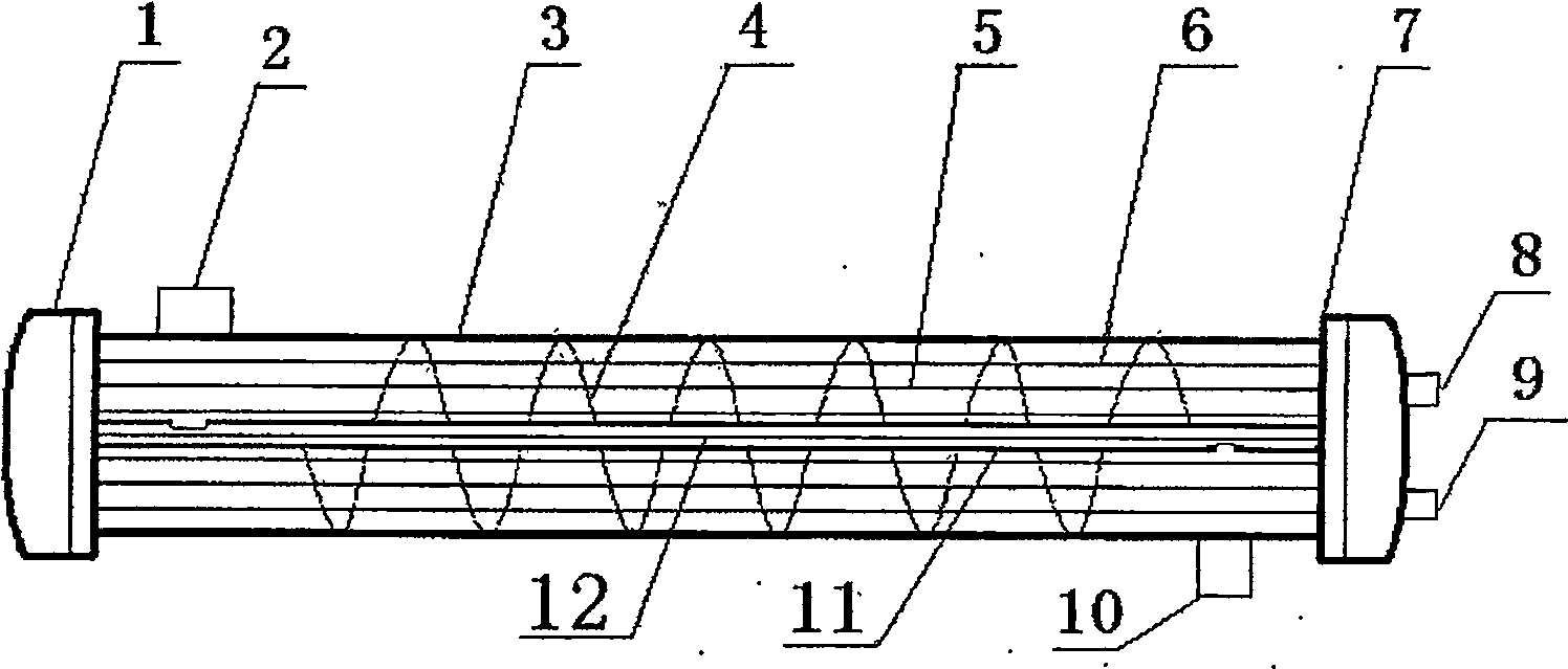
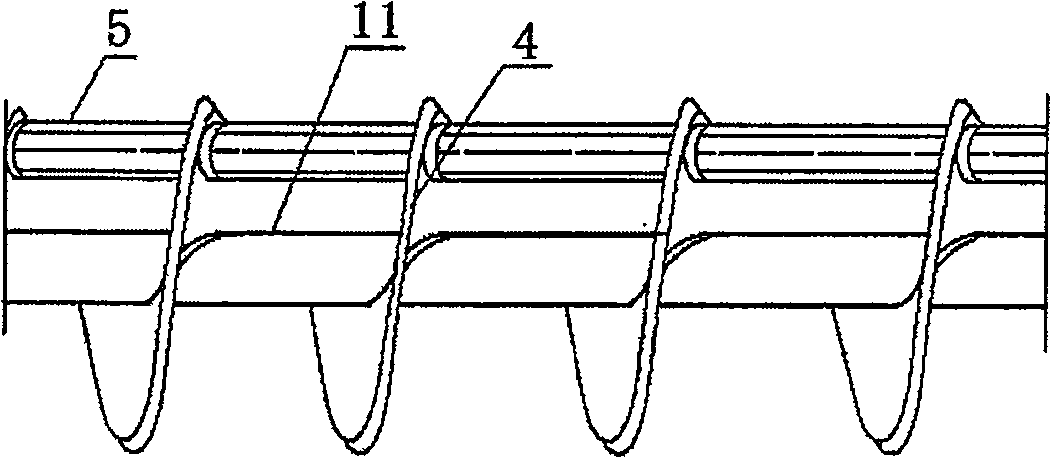
[0022] as attached figure 1 As shown, in this embodiment, the combined special-shaped tube bundle heat exchanger with continuous spiral baffles and double shell side is mainly composed of a head 1, a shell side inlet 2, a shell 3, a continuous spiral baffle 4, and the first tube bundle in the first tube bundle. A heat transfer tube 5, spacer tube 6, tube plate 7, tube side outlet 8, tube side inlet 9, shell side outlet 10, central tube 11, second heat transfer tube 12 in the second tube bundle. A continuous spiral baffle 4 , a first heat transfer tube 5 , a spacer tube 6 , a central tube 11 and a second heat transfer tube 12 are arranged between the tube sheets 7 . The first heat transfer tube 5 and the spacer tube 6 pass through the continuous spiral baffle 4 , and their two ends are respectively c...


PUM


Abstract

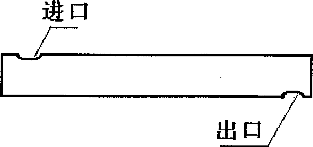
The invention discloses a special-shaped tube bundle heat exchanger with continuous spiral baffle double-shell side combination. The head at one end is provided with a tube pass inlet and a tube pass outlet, and one of the tube bundles and one of the tube bundles are also arranged between the tube sheets. Two; one of the tube bundles is composed of one of a plurality of heat transfer tubes, arranged between the central tube and the shell; the second tube bundle is composed of two of a plurality of heat transfer tubes, arranged in the central tube; one of the heat transfer tubes is a non- Special-shaped tubes with smooth walls, the second of the heat transfer tubes is a spiral flat tube; one of the fixed-distance tubes and the tube bundle passes through the spiral baffle, and its two ends are respectively connected with the tube sheet, and the spiral baffle is fixed by the fixed-distance tube; the tube bundle The two ends of the second are also respectively connected with the tube sheet; there are two notches corresponding to the shell-side inlet and the shell-side outlet of the heat exchanger respectively on the central tube. The heat exchanger of the present invention adopts two tube bundles with different heat transfer tube structures, less fluid back-mixing, no flow dead zone, little influence of bypass flow and leakage flow, and can make full use of the diameter of the shell to arrange heat transfer tubes. High thermal coefficient.

Description

technical field [0001] The invention relates to the technical field of heat exchangers, in particular to a continuous spiral baffle heat exchanger. Background technique [0002] There are many structures of heat exchangers used in industry. In terms of the structure of the support between the tubes, there are mainly single-bow baffles, double-bow baffles, and disc-ring baffles. The commonly used heat exchangers are single-bow baffles. There are many structures of baffles supporting tube bundles, and the heat transfer tubes are mainly smooth heat transfer tubes. In the bow-shaped baffle heat exchanger, the fluid flows back and forth between the baffles to scour the tube bundle. The fluid body resistance and pressure drop caused by the baffle are large, and it is easy to cause the vibration damage of the tube bundle. At the same time, the heat transfer coefficient of the smooth tube is low, which also leads to poor heat transfer performance of the heat exchanger. The spiral ...

Claims


Application Information

Patent Timeline
Patent Type & Authority Patents(China)
IPC IPC(8): F28D7/10
Inventor 张正国陆应生高学农
Owner SOUTH CHINA UNIV OF TECH
Learn More