Stabilizing mechanism for hoisting shaft cage and stabilizing device

A technology of cage lifting and tank stabilization, which is applied to lifting equipment, transportation and packaging in mines, can solve problems such as large up and down movement, and achieve the effects of reducing dynamic load, simple structure, and convenient installation and debugging.

Inactive Publication Date: 2009-08-26
CHINA COAL SCI & TECH GRP NANJING DESIGN & RES INST CO LTD
View PDF6 Cites 2 Cited by
  • Summary
  • Abstract
  • Description
  • Claims
  • Application Information

AI Technical Summary

Problems solved by technology

[0007] The technical problem to be solved by the present invention is to overcome the technical defects existing in the prior art. In order to solve the problem of large up and down movement of cages in deep wells and large wells during loading and unloading, the present invention provides a tank stabilizing mechanism and stabilizing mechanism for vertical shaft cage lifting. Tank device

Method used


Image

  • Stabilizing mechanism for hoisting shaft cage and stabilizing device
  • Stabilizing mechanism for hoisting shaft cage and stabilizing device
  • Stabilizing mechanism for hoisting shaft cage and stabilizing device

Examples


Embodiment 1

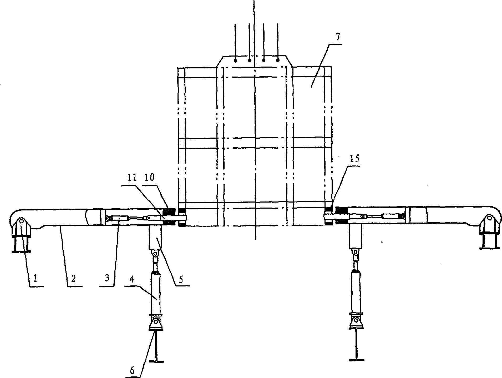
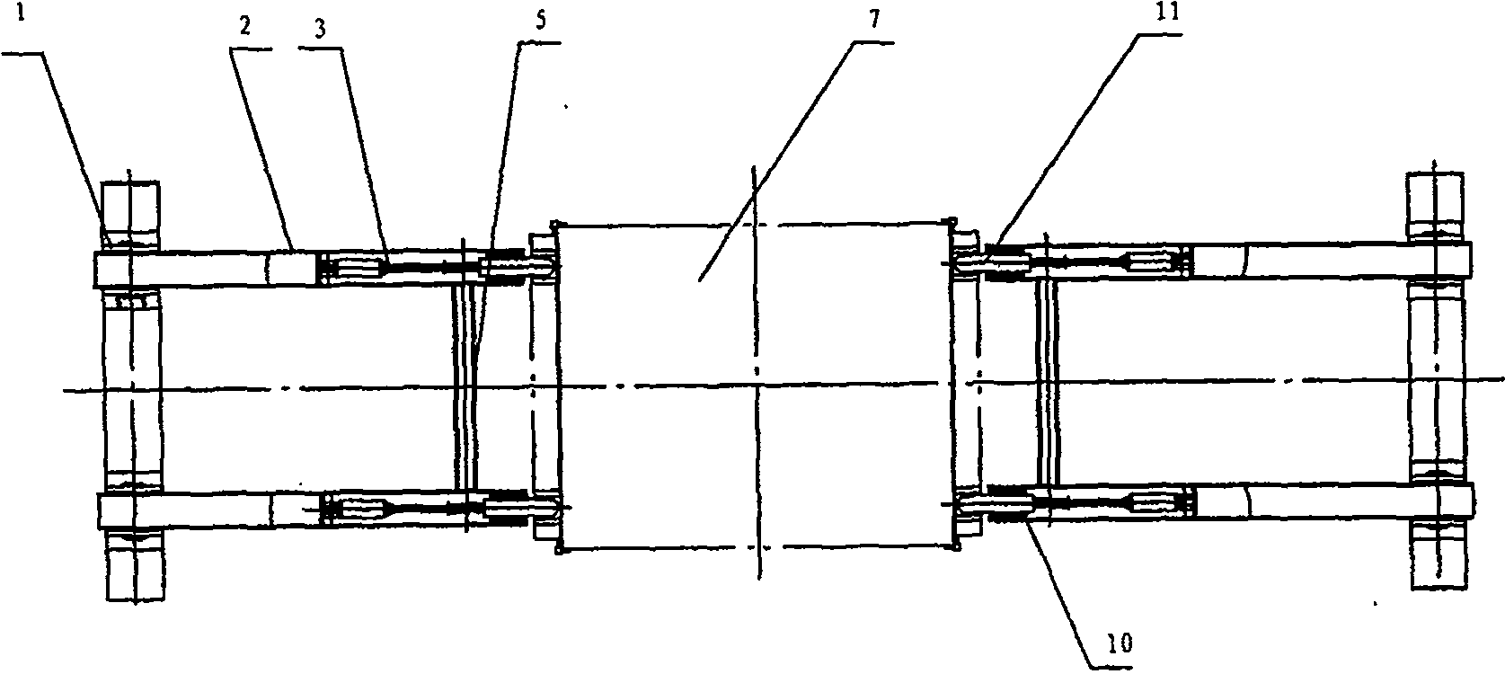
[0019] Example 1: The tank stabilization device for lifting the vertical shaft cage is used in conjunction with the shaking table 18 . Among them, the tank stabilization mechanism for the vertical shaft cage lifting is composed of a support 1, a tank stabilization arm 2, a catcher, and a buffer cylinder 4; the tank stabilization arm is hinged with the support; The rod 11 is formed, the oil cylinder 3 is hinged on the tank stabilizing arm, the oil cylinder 3 is hinged with the push rod 11, and the push rod 11 passes through the sliding seat 10 at the front end of the tank stabilizing arm; the buffer cylinder 4 is supported under the front part of the tank stabilizing arm. The tank stabilization device is composed of the two sets of tank stabilization mechanisms. The tank stabilization mechanisms are arranged in parallel. The front parts of the two tank stabilization arms of the tank stabilization mechanism are connected together by a beam 5. The buffer cylinder 4 is supported on...

Embodiment 2

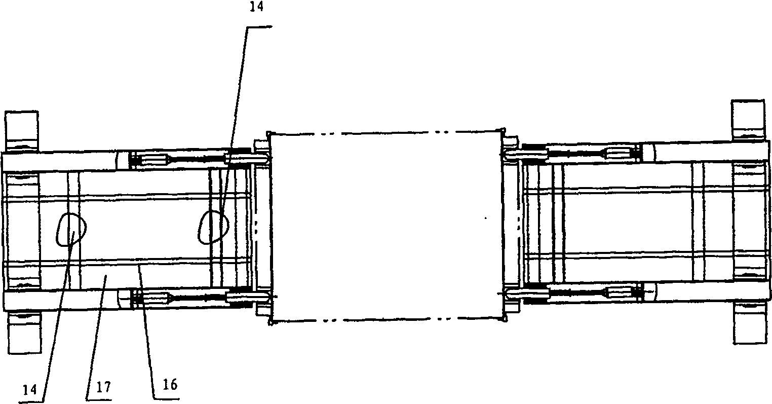
[0020] Example 2: The tank stabilization device of the present invention is used alone as a tank holding device. The structure of the tank stabilization device is the same as that of Example 1. The difference is that the cylinder 3 is replaced by an air cylinder, and the buffer cylinder 4 is replaced by a buffer cylinder; The device is also used symmetrically. Two sets of tank stabilization devices are arranged on the entry and exit sides of the cage respectively. The lengths of the tank stabilization arms on both sides can be the same or different depending on the actual situation. There are two identically constructed tank stabilizing arms on each side. The tank stabilizing arm is a welded steel beam, which is connected to the support 1 through a pin, and can swing up and down around the pin. The cylinder 3 of the catcher is connected to the support 8 through a pin shaft, and the front end of the cylinder is connected to the push rod 11 through a pin shaft, and the push ro...


PUM


Abstract

The invention discloses a tank stabilizing mechanism for lifting a shaft cage, which is composed of a support, a tank stabilizing arm, a catcher, a buffer oil cylinder or a buffer cylinder; the tank stabilizing arm is hinged to the support; the catcher is installed on the tank stabilizing arm , consisting of an oil cylinder or cylinder and a push rod, the oil cylinder or cylinder is hinged on the stabilizer arm, the oil cylinder or cylinder is hinged to the push rod, and the push rod passes through the sliding seat at the front end of the stabilizer arm; the buffer oil cylinder or buffer cylinder is supported on the stabilizer arm the lower part of the front. The tank stabilizing device is composed of two sets of tank stabilizing mechanisms, which are arranged parallel to each other, and the front parts of the two tank stabilizing arms are connected as a whole with a beam. The invention has simple structure and convenient installation and debugging. Through the use of this equipment, the cage can be locked in a horizontal position during loading and unloading, avoiding the sudden up and down movement of the cage due to elastic changes during loading and unloading, and ensuring smooth loading and unloading; And smoothly release the energy of the cage moving up and down, greatly reducing the dynamic load brought by the hoisting wire rope due to loading and unloading.

Description

Technical field [0001] The invention is a device in a mine shaft hoisting system, and relates to a tank stabilizing device used for hoisting cages in mine shafts to prevent excessive movement of the cages up and down from affecting normal loading and unloading, and is especially suitable for hoisting cages in deep shafts and heavy equipment shafts. used in. Background technique [0002] In vertical shaft cage lifting, a carrier device is required to connect the cage to the track in the tunnel. At present, the main tank supporting devices used in mines are: shaking table, tank support machine, and tank seat; the shaking table is the most widely used, which is a movable track that can swing around a fixed axis. Its advantage is that it can realize suspended loading, except for part of its own weight, it will not add additional load to the cage and the lifting wire rope; the action is fast and the rest time is short. Its disadvantages are: first, the tank stop is not very acc...

Claims


Application Information

Patent Timeline
Patent Type & Authority Patents(China)
IPC IPC(8): B66B17/00
Inventor 胡泉灵荆炜华王春奇史爱民罗广群王汝辉
Owner CHINA COAL SCI & TECH GRP NANJING DESIGN & RES INST CO LTD
Why Eureka
Try Eureka