
Brush holder for an electrical machine

A brush holder and brush technology, which is applied to circuits, current collectors, electrical components, etc., can solve problems such as brush noise, and achieve the effect of simple structure and large cost saving potential.

Inactive Publication Date: 2009-08-19
ROBERT BOSCH GMBH
View PDF2 Cites 0 Cited by
  • Summary
  • Abstract
  • Description
  • Claims
  • Application Information

AI Technical Summary

Problems solved by technology

This causes so-called brush noise during operation

Method used


Image

  • Brush holder for an electrical machine
  • Brush holder for an electrical machine

Examples


Embodiment Construction

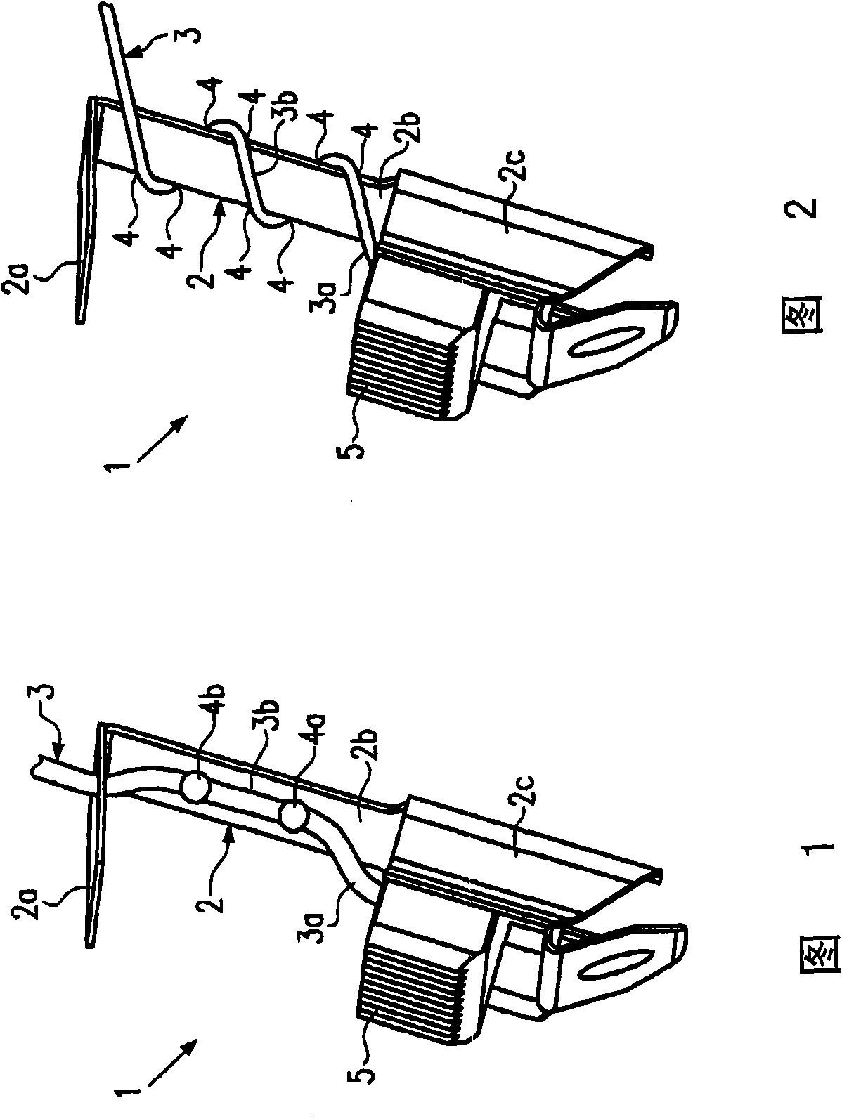
[0020] Refer below figure 1 A brush holder 1 according to a first exemplary embodiment of the invention will be described. The brush holder 1 essentially comprises a spring rod 2 which is made, for example, of spring steel or plastic with elastic properties. The spring lever 2 includes a fastening region 2 a with which the spring lever 2 is fastened, for example, to the housing of the electric motor. The fastening region 2 a can be clamped, for example, into a housing region or cast into the housing region by injection molding. Furthermore, the spring rod 2 also includes a rod region 2b which extends at a predetermined angle with respect to the fixing region 2a. At the end of the shaft region 2b, a bearing region 2c for supporting a brush 5 is provided. Such as figure 1 As shown, the brush 5 protrudes slightly forward from the support area 2c and provides electrical contact with a rotating structural part of the motor.

[0021] The brushes 5 can be supplied with current v...


PUM


Abstract

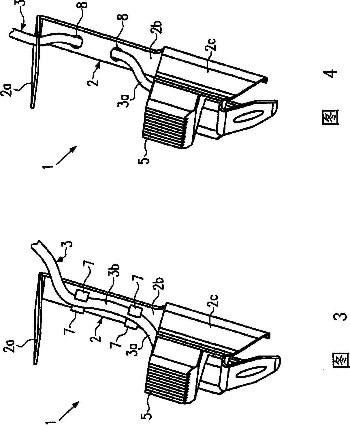
The invention relates to a brush holder for an electric motor, comprising: a spring bar element (2), on which a brush support (2c) for supporting a brush (5) is arranged; and A litz wire (3) for electrically conductive connection of the brush (5), wherein the litz wire (3) contacts the spring element (2) at at least one contact point (4a, 4b; 7; 8) in such a way , That is, a twisted wire portion (3a, 3b) having a predetermined length is formed between the contact portion and the brush (5) to damp vibration occurring on the brush holder.

Description

technical field [0001] The invention relates to a brush holder for an electric machine and to an electric machine with such a brush holder. Background technique [0002] The prior art already discloses brush holders for electric motors in different versions. In this case the brush holder has the function of supporting the carbon brushes for making electrical contact between the stationary part and the rotating part. In this case, brush vibrations occur during the operation of the motor. This type of brush vibration is caused in particular by fluctuations in the coefficient of friction. These vibrations can be guided by the brush holder into other components of the motor and radiated to the environment. This causes so-called brush noise during operation. Especially when such motors are used, for example, in motor vehicles as comfort drives for window lifters, electric sunroofs, seats, etc., such noises are undesirable during operation, since the noises are felt by the veh...

Claims


Application Information

Patent Timeline
Patent Type & Authority Patents(China)
IPC IPC(8): H01R39/39
CPCH01R39/39H02K5/14
Inventor B·鲁普
Owner ROBERT BOSCH GMBH
Learn More