Plastic injecting mold for casting system with low power consumption

A pouring system and injection mold technology, applied in the field of plastic molds, can solve the problems of difficult mold maintenance, long cycle time, difficult automatic shedding of nozzle materials, and easy removal of nozzle crochets. effect of life

Inactive Publication Date: 2009-08-19
李岳桥 +3
View PDF3 Cites 0 Cited by
  • Summary
  • Abstract
  • Description
  • Claims
  • Application Information

AI Technical Summary

Problems solved by technology

[0007] The object of the present invention is to provide an energy-saving and consumption-reducing pouring system with short main channel, automatic drop-off of nozzle material, no damage to product appearance at the gate position, no need for reprocessing after molding, reinforced mold movable parts and easy replacement and maintenance. Plastic injection molds to solve the problems in the existing plastic injection mold gating system that the main channel is too long, the nozzle material is difficult to fall off automatically, the crochet needle at the nozzle is easy to move, the gate damages the product appearance or the gate position needs to be reprocessed, Problems such as difficult mold maintenance and long period

Method used


Image

  • Plastic injecting mold for casting system with low power consumption
  • Plastic injecting mold for casting system with low power consumption
  • Plastic injecting mold for casting system with low power consumption

Examples


Embodiment Construction

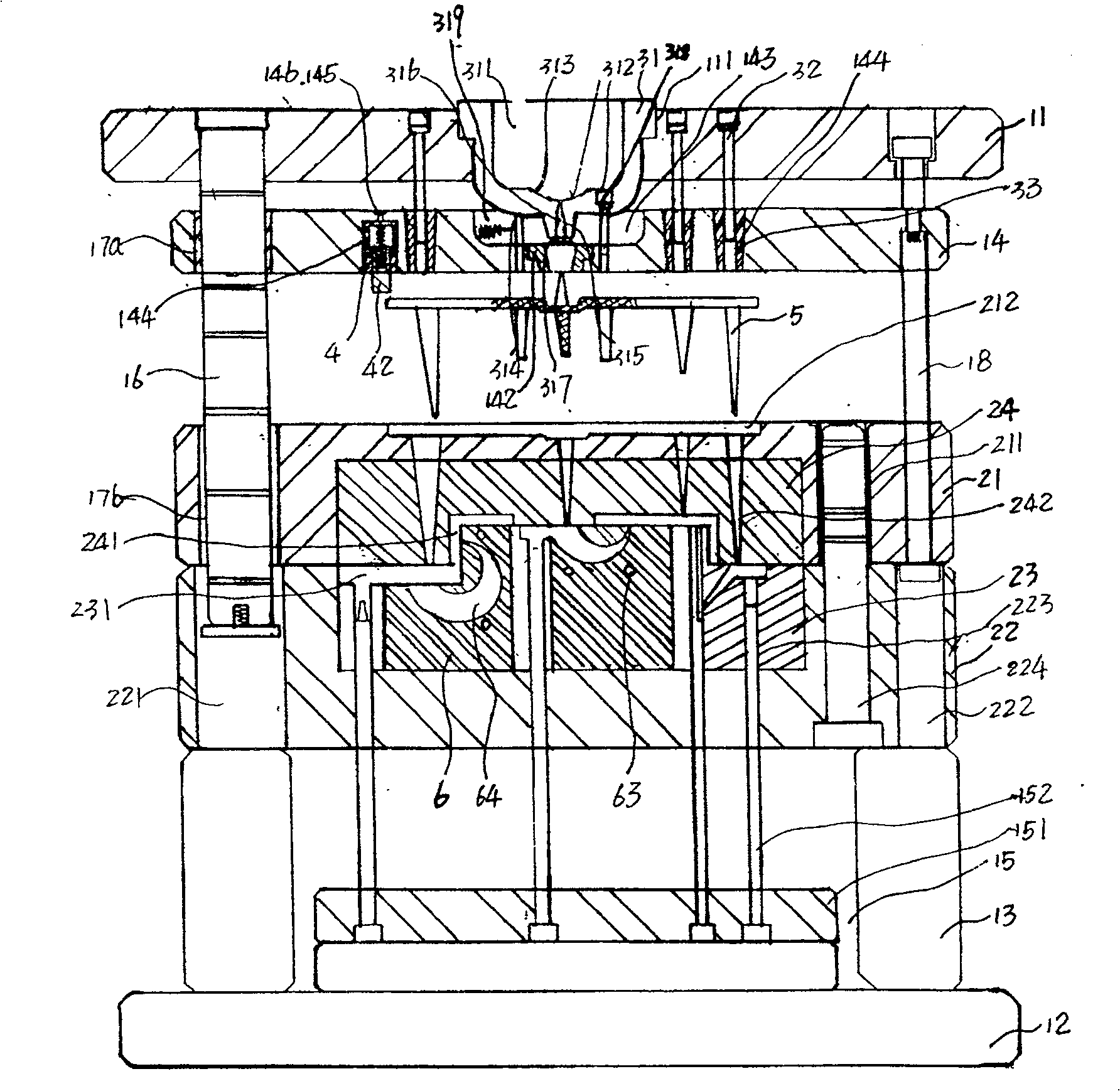
[0036]See figure 1 , A plastic injection mold with an energy-saving and consumption-reducing gating system, including a mold composed of an upper template 11, a lower template 12, a mold foot 13, a stripper plate 14, an ejection member 15, a guide post 16, and a guide sleeve 17a, 17b Frame; a molding part composed of cavity A plate 21 and cavity B plate 22, and male and female molds 23 and 24 installed in cavity A plate 21 and cavity B plate 22; pouring system.

[0037] The cavity B plate 22 is fixedly connected with the lower mold plate 12 through mold feet 13 and fasteners. The guide post 16 is fixedly installed on the upper mold plate 11 and passes through the guide sleeves provided on the stripper plate 14 and the cavity A plate 21 17a and 17b connect the upper template 11 with the stripper plate 14 and the cavity A plate 21; the stripper plate 14 and the cavity A plate 21 can slide on the guide post 16.

[0038] The stripper plate 14 is also equipped with tie rods 18 for div...


PUM


Abstract

A plastic injection mold with an energy-saving and consumption-reducing pouring system includes a mold base, molding parts, a pouring system, and a dual-purpose sprue bushing for the sprue bushing in the pouring system to shorten the sprue to an optimal length as much as possible. The front end of the sprue sleeve and the stripper plate are separated by a sheath to reduce repeated friction with the stripper plate and improve the service life of the mold. Install a cold material dropper on the stripper plate, use the elastic deformation of the spring to push the piston to bounce the nozzle material off the nozzle push plate, so that the nozzle material will fall off automatically. In order to avoid direct friction between the crochet needles and the stripper plate and reduce damage, a wear-resistant spout hook cover is provided between the stripper plate and the spout hooks. In order to solve the existing hidden gates, side gates, point gates, etc. that damage the product appearance, a number of horn-shaped inlaid inserts are embedded in the female mold, and a horn is set in the horn-shaped inlaid insert. The sprue in the shape of the sprue communicates with the point gate on the female mold and the molding cavity.

Description

Technical field [0001] The invention relates to a plastic mold, in particular to a plastic injection mold with an energy-saving and consumption-reducing pouring system. Background technique [0002] The current three-plate plastic mold generally includes a mold base composed of upper and lower mold plates, mold feet, stripper plates, ejector components, guide posts, and guide sleeves. It is composed of cavity A plate and cavity B plate and is installed in the cavity The molding parts composed of the female and male molds in the A plate and the cavity B, and the pouring system. The function of the gating system is to smoothly and smoothly fill the cavity with the molten plastic, so that the gas in the cavity can be discharged smoothly, and during the filling and solidification process, the pressure can be transmitted to all parts of the plastic part. Obtain tightly organized plastic parts. [0003] The existing gating system generally includes a sprue sleeve, a runner, a nozzle cr...

Claims


Application Information

Patent Timeline
Patent Type & Authority Patents(China)
IPC IPC(8): B29C45/27B29C45/26
Inventor 李岳桥左荣华李泳辉陈向阳
Owner 李岳桥
Why Eureka
Try Eureka