Hydrogen production technique

A process, methane technology, applied in the field of new hydrogen production process, to achieve the effect of reducing hydrogen production cost, reducing equipment investment and improving hydrogen production efficiency

Inactive Publication Date: 2009-08-05
王庆松 +1
View PDF3 Cites 0 Cited by
  • Summary
  • Abstract
  • Description
  • Claims
  • Application Information

AI Technical Summary

Problems solved by technology

[0003] The purpose of the present invention is to overcome the defect that excessive high-temperature and high-pressure steam must be used in the currently popular methane steam-water gas conversion combined hydrogen production process, and to provide a hydrogen production process using methane carbon dioxide catalytic reforming-water gas conversion. hydrogen process

Method used


Image

  • Hydrogen production technique
  • Hydrogen production technique
  • Hydrogen production technique

Examples


Embodiment 1

[0022] This example is the preparation and pretreatment of the methane carbon dioxide catalytic reforming catalyst A1 in the first step of the hydrogen production process of the present invention.

[0023] Dissolve 29.5g of nickel nitrate, 130g of aluminum nitrate, 0.1g of potassium nitrate, and 290g of magnesium nitrate in 1000ml of deionized water, mix it with ammonia water under stirring, and control the pH to 9±1, filter and wash the resulting precipitate, and put it at 120± Dry at 10°C for 12 hours, and bake at 900±20°C for 10 hours to obtain methane carbon dioxide reforming catalyst A1: NiAl 4.5 K 0.01 Mg 9.2 o 16.96 .

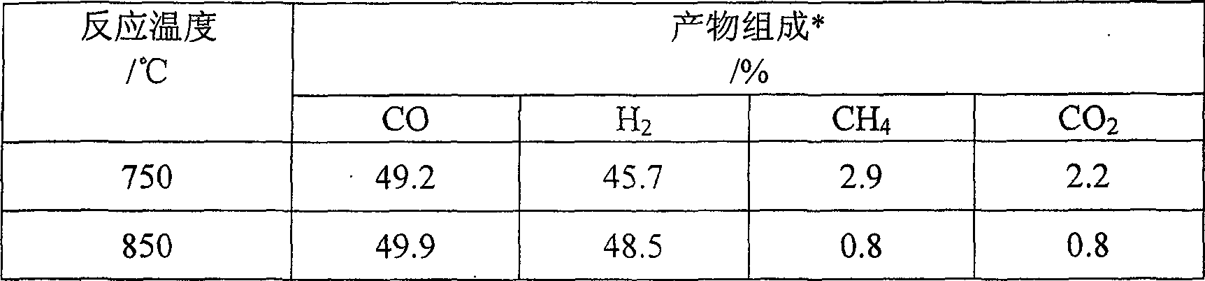
[0024] Take 0.1ml of Catalyst A1 of 40-60 meshes and mix it with 0.3ml of quartz sand evenly, put it into a quartz reactor with a diameter of 5mm and a length of 40mm, purge the reaction system with nitrogen, and then dilute it with nitrogen at a flow rate of 100ml / min. hydrogen, the hydrogen concentration is 10-20% (volume concentration), and the re...

Embodiment 2

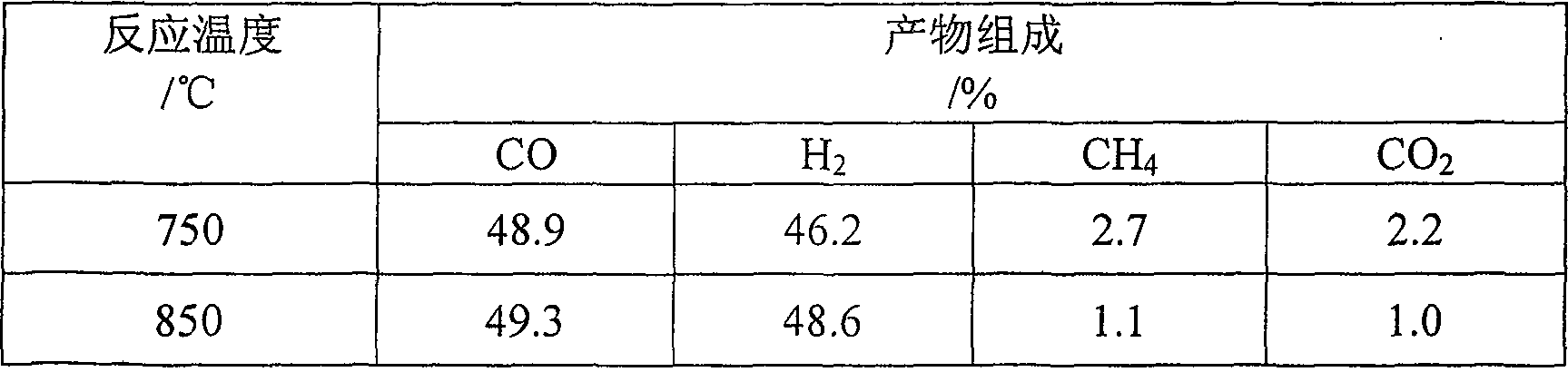
[0026] This example is the preparation and pretreatment of the methane carbon dioxide catalytic reforming catalyst A2 in the first step of the hydrogen production process of the present invention. Dissolve 29.5g nickel nitrate, 130g aluminum nitrate, 24.5g cobalt nitrate, 187g zirconium nitrate in 1000ml deionized water, mix with ammonia water under stirring, control pH=9±1, filter and wash the generated precipitate, and put Dry at 10°C for 12 hours, and bake at 900±20°C for 10 hours to obtain methane carbon dioxide reforming catalyst A2: NiAl 4.5 CoZ 5.0 o 13.75 .

[0027] The reduction pretreatment conditions of catalyst A2 were the same as those of catalyst A1 in Example 1.

Embodiment 3

[0029] This example is the preparation and pretreatment of the methane carbon dioxide catalytic reforming catalyst A3 in the first step of the hydrogen production process of the present invention. Dissolve 29.5g nickel nitrate, 130g aluminum nitrate, 0.1g potassium nitrate, 187g zirconium nitrate in 1000m1 deionized water, mix with ammonia water under stirring, control pH=9±1, filter and wash the generated precipitate, and put it at 120± Dry at 10°C for 12 hours, and bake at 900±20°C for 10 hours to obtain methane carbon dioxide reforming catalyst A3: NiAl 4.5 K 0.01 Zr 5.0 o 12.76 .

[0030] The reduction pretreatment conditions of catalyst A3 are the same as the reduction pretreatment conditions of catalyst A1 in Example 1.


PUM


Abstract

The invention relates to a hydrogen production process, in particular to a hydrogen production process combined with catalytic reforming of methane and carbon dioxide-water gas conversion. It includes: 1) feeding the mixed gas of methane and carbon dioxide into the reactor, and contacting with the metal composite oxide catalyst with the general formula NiaAlbMmNnOx, wherein a is 0.1-1.0, b is 2.0-6.0, m is 0.001-1.0, and n is 0.1~10.0, x is the number of oxygen atoms that meet the valence requirements of other elements, M is selected from Na, K, Mo, Zn, Co, Cr, Ru, Rh; N is selected from Ca, Ce, Zr, Ti, Mg; process conditions It is: temperature 500~1000℃, pressure 1~10atm, molar ratio of methane / carbon dioxide 0.5~5.0, gas hourly space velocity, 1,000~150,000h-1; 2) Mix the product of step 1) with water vapor and pass it into the reactor and Water-gas shift catalyst contact, the process conditions are: temperature 170-450°C, pressure 1-10atm, water vapor / carbon monoxide molar ratio 1-5, gas hourly space velocity 1,000-100,000h-1. The invention does not need excessive high-temperature and high-pressure water vapor and high-pressure equipment, so that energy consumption and equipment investment are reduced, and the source of raw materials is extensive, and carbon dioxide does not need to be separated.

Description

1. Technical field [0001] The invention relates to a hydrogen production process, in particular to a novel hydrogen production process which combines catalytic reforming of methane and carbon dioxide and water gas conversion to produce hydrogen. 2. Background technology [0002] Hydrogen is both a clean energy source and an important industrial gas. Among the current hydrogen production processes, the most mature, stable and low-cost process is the methane steam reforming-water gas shift combined hydrogen production process. The methane steam reforming-water gas shift combined hydrogen production process is mainly divided into four steps: 1) methane purification to remove impurities such as sulfur; 2) methane and high-temperature steam are mixed with Ni 3) The mixed gas of hydrogen and carbon monoxide generated in the second step and low-temperature water vapor are respectively contacted with the Fe-Cr oxide catalyst at 300-450 °C and 180-270 °C. Contact with Cu-Zn oxide c...

Claims


Application Information

Patent Timeline
Patent Type & Authority Patents(China)
IPC IPC(8): C01B3/40
Inventor 张建国王庆松
Owner 王庆松
Why Eureka
Try Eureka