Dynamic separator
A separator and dynamic technology, applied in the field of coal mills, can solve the problems of increasing the internal circulation load and reducing the separation efficiency of the grinding mill
- Summary
- Abstract
- Description
- Claims
- Application Information
AI Technical Summary
Problems solved by technology
Method used
Image
Examples
Embodiment Construction
[0020] The present invention will be described in further detail below in conjunction with the accompanying drawings.
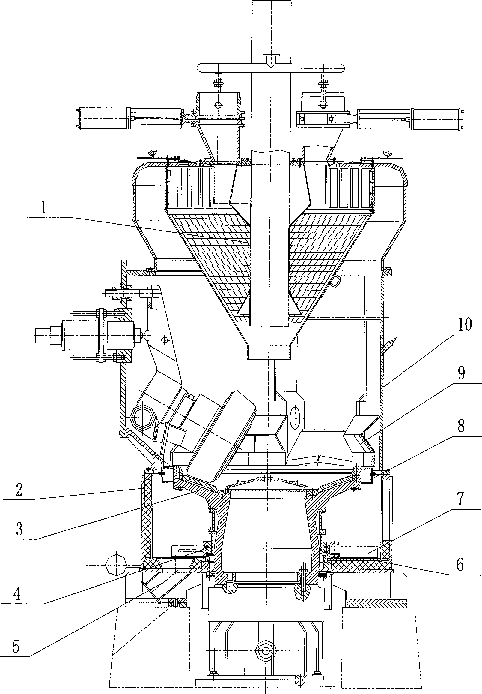
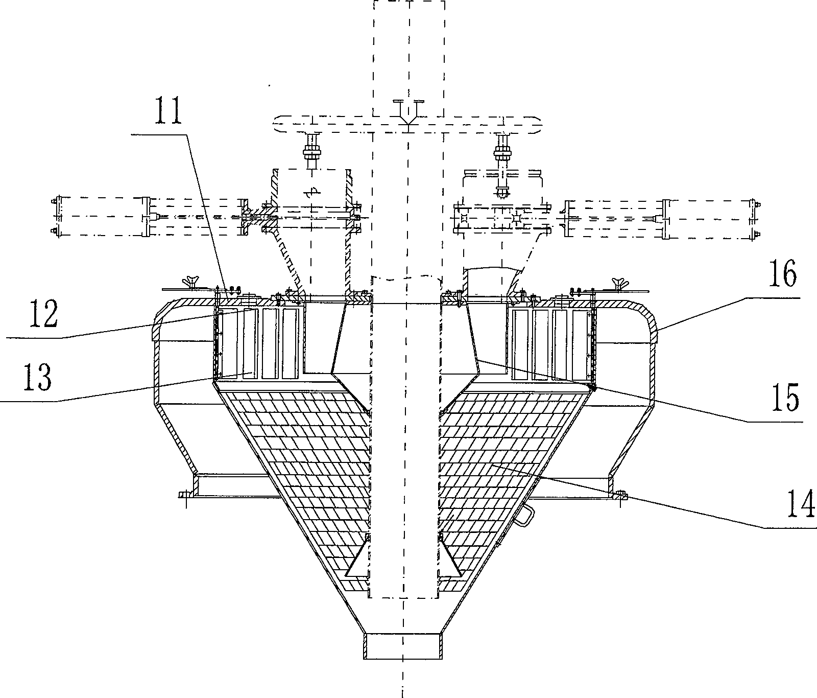
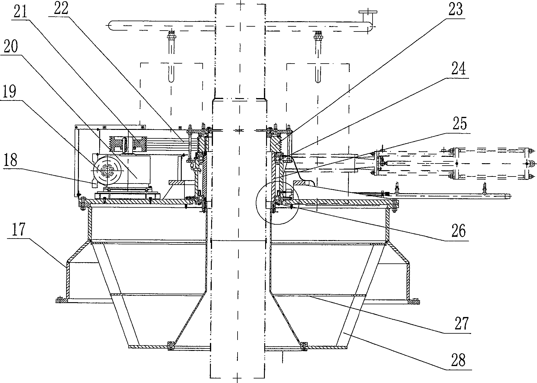
[0021] The dynamic separator 32 of the present invention is as image 3 As shown, it includes dynamic separator top cover 17, frequency converter 18, frequency conversion motor 19, worm gear reducer 20, driving wheel 21, V-belt 22, driven wheel 23, rotor device 27, blade 28, driving device 26, bearing seat 25 and a pair of bearings 24; the variable frequency motor 19 and the worm gear reducer 20 are connected together through a coupling, and the driving wheel 21 is installed on the output shaft of the worm gear reducer 20, driven by the V-belt 22 and connected to the rotor device 27 The driven wheel 23 together, thus the blade 28 welded together with the rotor device rotates, and the rotation direction of the blade 28 is clockwise when viewed from the top of the coal mill. The rotor device 27 is located inside the top cover 17 of the separator, and is flange...
PUM
 Abstract
Description
Claims
Application Information
 - R&D Engineer
- R&D Manager
- IP Professional
- Industry Leading Data Capabilities
- Powerful AI technology
- Patent DNA Extraction
Browse by: Latest US Patents, China's latest patents, Technical Efficacy Thesaurus, Application Domain, Technology Topic, Popular Technical Reports.
© 2024 PatSnap. All rights reserved.Legal|Privacy policy|Modern Slavery Act Transparency Statement|Sitemap|About US| Contact US: help@patsnap.com


