
Indoor air control regulation system

A technology for controlling and regulating indoor air, which is applied in the field of indoor air control and regulating systems, and can solve problems such as the spread of oil fume, the inability of the fume extraction equipment to quickly discharge it, and the inability to control the direction of gas flow well, so as to achieve the effect of reducing energy consumption

Inactive Publication Date: 2009-07-15
王君
View PDF5 Cites 0 Cited by
  • Summary
  • Abstract
  • Description
  • Claims
  • Application Information

AI Technical Summary

Problems solved by technology

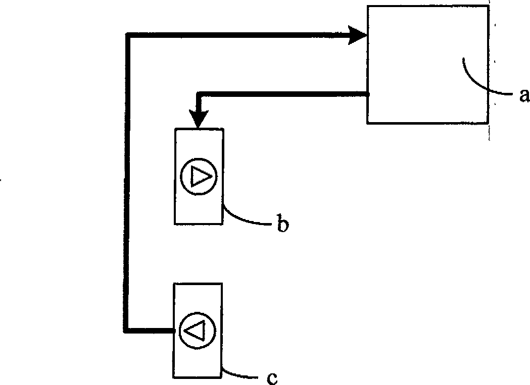
Although the exhaust outlet c can reduce the pressure of the indoor air, the active pressurized air supply still occupies a dominant position, resulting in a lack of comfort for people in the room
In this state, the indoor air basically cannot achieve directional flow according to people's needs, so the air circulation and air flow in residential and office spaces are not ideal.
[0006] In residential buildings, kitchens and bathrooms usually use one-way exhaust devices and fume extraction equipment to forcibly discharge air to create negative pressure so that odors and fumes cannot flow to other rooms, but the effect is not ideal
The reason is that these devices only have a certain effect on a certain area point, but cannot control the air pressure distribution in each area of ​​the entire building unit. Therefore, when a large amount of gas containing other substances is generated, these gases cannot be well controlled. direction of flow
The instant cooking fume in the kitchen will prevent the fume extraction equipment from quickly exhausting it, causing the cooking fume to spread to other rooms, and it will take a long time to be completely cleared.
In addition, the operation of special exhaust equipment will also bring a lot of noise, forming noise pollution in the indoor environment

Method used


Image

  • Indoor air control regulation system
  • Indoor air control regulation system
  • Indoor air control regulation system

Examples


Embodiment 1

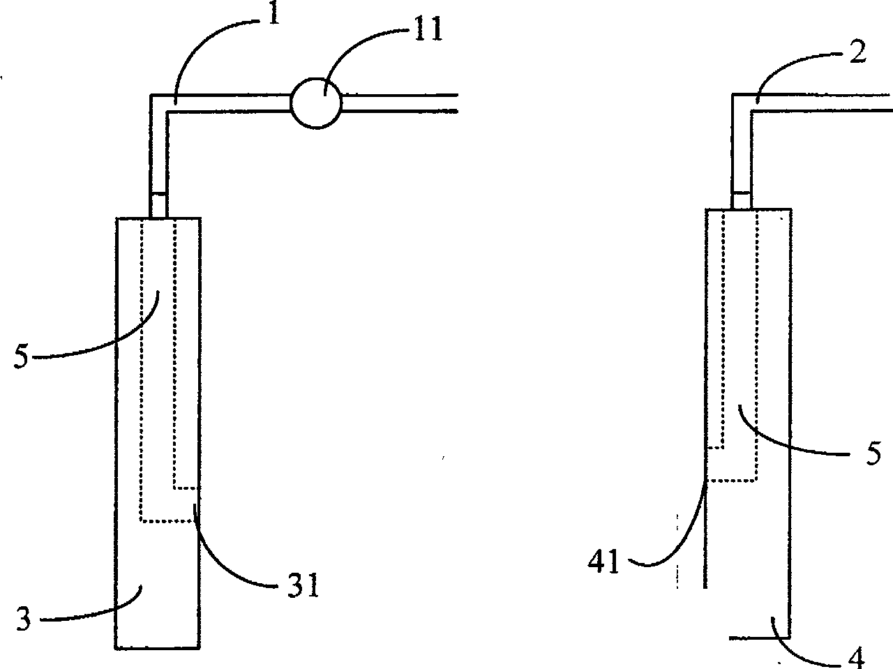
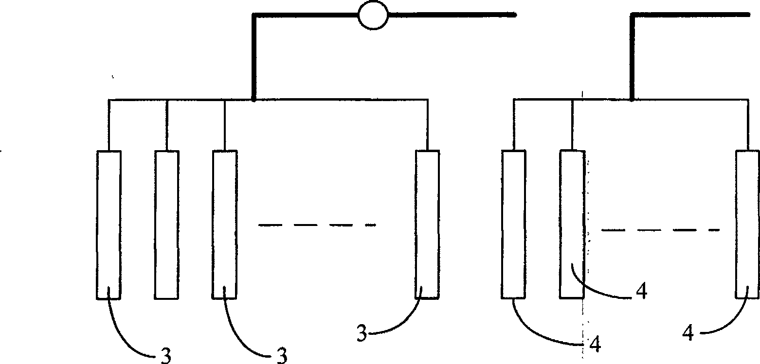
[0044] figure 2 Shown is a basic system structure of the present invention, the system includes an exhaust duct 1 , an air supply duct 2 and a negative pressure fan 11 arranged in the exhaust duct 1 . One end of the exhaust duct 1 is connected to a negative pressure device 3 with an air flow channel 5 inside, and an air exhaust port 31 is provided on the surface of the negative pressure device 3 at the air flow channel 5 . One end of the air supply duct 2 is connected to a pressure supplementing device 4 with an airflow channel 5 inside, and an air supply port 41 is provided on the surface of the pressure supplementation device 4 at the airflow channel 5 .

[0045] The exhaust pipe 1, the negative pressure fan 11 and the negative pressure device 3 constitute a negative pressure subsystem, while the air supply pipe 2 and the pressure supplement device 4 constitute a pressure supplement subsystem. Negative pressure fan 11 sucks indoor air through air outlet 31 after starting, ...

Embodiment 2

[0050] Such as Figure 4 As shown, in this embodiment, both the negative pressure device 3 and the pressure supplementing device 4 are hollow plates. The hollow board body can be made into a wallboard for decoration, and can also be made into a furniture panel. The structural form of the airflow channel 5 can adopt various forms. In this embodiment, the upper and lower ends of the airflow channel 5 in the negative pressure device 3 have air confluence parts, and the middle part is a wide channel. The air outlet 31 can be arranged at the wide channel, and can also be arranged at the confluence part at the same time. The air flow passage 5 in the pressure supplementing device 4 also has air confluence parts at the upper and lower ends, and the middle part is a plurality of narrow passages. Likewise, the air supply port 41 can also be arranged on the air converging part or on the channel. The plate-shaped negative pressure device 3 and the pressure-replenishing device 4 with ...

Embodiment 3

[0055] Such as Figure 7 As shown, the difference between this embodiment and the above-mentioned two embodiments is that an air temperature adjustment device 7 and a pressure supplement fan 21 are provided at the connection between the pressure supplement device 4 and the air supply duct 2 . Air temperature adjustment device 7 can adopt existing refrigeration, heating device, such as compressor, electric heater etc., heat exchanger can also be set in air temperature adjustment device 7, make the air that flows through and the cooling in the heat exchanger. Heat exchange is performed between the heat media, thereby adjusting the temperature of the air. Since the air flowing through needs to have a certain pressure during the heat exchange process of the air, a supplementary pressure blower 21 is provided to push the supplementary air. The air after heat exchange is sent into the airflow channel in the pressure supplementing device 4 . When the negative pressure fan 11 is sta...


PUM


Abstract

The invention relates to an indoor air control and regulating system, which comprises an air exhaust pipe, an air supply pipe and a negative-pressure air fan. One end of the air exhaust pipe is connected with one or more than one negative-pressure device(s) provided internally with an airflow channel, and the surface of the negative-pressure device at the airflow channel is provided with an air outlet; One end of the air supply pipe is connected with one or more than one pressure-filling device(s) provided internally with an airflow channel, and the surface of the pressure-patching device at the airflow channel is provided with an air supply outlet. By utilizing the negative-pressure device and the pressure-filling device with airflow channels, and through the connection of the pipes and the negative-pressure air fan, the invention realizes the flow of indoor air between surface and surface, point and point as well as point and surface. Under the action of a purifying device, the indoor air is purified, reducing and eliminating the harmful materials and germs in the air. After an air temperature regulating device is arranged, the indoor temperature can be regulated effectively and the energy source consumption is reduced greatly.

Description

technical field [0001] The invention relates to an indoor air control and adjustment system, especially one that is installed in the form of decoration parts or furniture parts on indoor decoration and furniture, and can control and adjust the flow direction and temperature of indoor air according to user needs. system. Background technique [0002] Whether it is office space, living space or leisure space, people have higher and higher requirements for air quality. How should the polluted air produced by office equipment (such as copiers, etc.) How to completely separate from the air in the non-smoking area has become a widely concerned issue. With the gradual improvement of people's requirements for working and living environments in modern society and the continuous strengthening of the functionality of modern buildings, people began to pay attention to the flow of indoor air on the premise of caring about indoor temperature and air quality. [0003] Since the air alwa...

Claims


Application Information

Patent Timeline
Patent Type & Authority Patents(China)
IPC IPC(8): F24F7/06F24F7/10F24F3/16
Inventor 王君
Owner 王君
Learn More