Sail wing for increasing lift force and stalling attack angle

A technology for stalling angle of attack and increasing lift, applied in the field of aviation

Inactive Publication Date: 2009-07-15
朱上翔
View PDF7 Cites 0 Cited by
  • Summary
  • Abstract
  • Description
  • Claims
  • Application Information

AI Technical Summary

Problems solved by technology

From the published results, it can be clearly seen that the stall angle of attack and the lift coefficient in the linear section are almost unchanged with or without the installation of the olecranon vortex generator, and only the post-stall characteristics after the stall are slightly improved.

Method used


Image

  • Sail wing for increasing lift force and stalling attack angle
  • Sail wing for increasing lift force and stalling attack angle
  • Sail wing for increasing lift force and stalling attack angle

Examples


Embodiment Construction

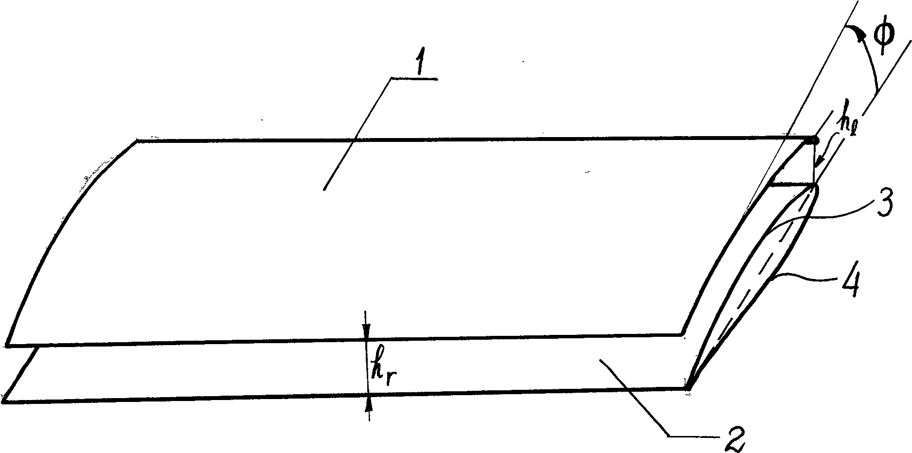
[0013] Depend on figure 1 It can be seen that the awning wing 1 is located above the upper airfoil surface 3 of the wing 2 . The leading edge and trailing edge of the awning wing and wing are parallel to each other along the span direction, but along the chord direction, the distance between the lower surface of the awning wing and the upper surface of the wing is not necessarily equal. h r is the relative height of the canopy to the trailing edge of the wing. h 1 is the relative height of the canopy to the leading edge of the wing. When H r =H 1 , the upper surface 3 of the awning wing 1 and the wing is parallel to each other. When H r ≠ H 1 , the canopy wing has an installation angle Φ relative to the wing. The Φ angle is the angle between the line connecting the front and rear edges of the canopy and the wing chord. Φ is changed (usually positive) by changing H 1 (fixed H r ) to achieve. h 1 The size will affect the lifting effect of this device. Through calc...


PUM


Abstract

The invention discloses an awning wing for increasing the lift force and the stall angle of attack, which is a thin fin structure placed on top or obliquely above the upper surface of the wing. A ventilation duct is formed in front of the canopy and the upper surface of the wing, which delays the separation of the airflow, increases the stall angle of attack of the entire wing, and greatly increases the maximum lift coefficient of the whole aircraft. Comparing the wind tunnel test data of the aircraft model with awnings with the situation without awnings, it is found that the maximum lift coefficient has increased by more than 70%, and the stall angle of attack has increased by more than 8°-18°. When flying, the wing can be released or retracted as required. When retracted, the awning is stored on the upper surface of the basic airfoil to keep the profile of the original airfoil unchanged. The canopy wing is novel in principle and simple in structure, and can be widely used in civil and military aircraft or other machines moving in fluid.

Description

technical field [0001] The invention relates to aviation technology, more specifically, relates to a canopy wing which can be used for increasing the lift force and the stall angle of attack of an aviation vehicle. Background technique [0002] In order to make the aircraft obtain sufficient lift when flying at a low speed, almost all aircraft are equipped with a lift-increasing device. The high-lift device of prior art mainly contains following several: the most common device is various types of flaps, comprises the slotted flap of early stage of aircraft development and the Fuller flap and Kruger flap that successively invented later. Fuller flaps are flaps mounted on the trailing edge of the wing. Kruger flaps are flaps mounted on the leading edge of the wing. There are many types classified by structure, such as split flaps, simple flaps, and slotted flaps. The main function of these flaps is to increase the camber of the airfoil to delay the separation of the airflow...

Claims


Application Information

Patent Timeline
Patent Type & Authority Patents(China)
IPC IPC(8): B64C3/00B64C23/06B64C3/54
CPCB64C3/54
Inventor 朱上翔
Owner 朱上翔
Why Eureka
Try Eureka