
Device for clamping components

A component and equipment technology, applied in the field of equipment for welding the components, can solve the problems of high cost, increased heat loss in the seam formation area, and the inability of the planar vacuum clamping table to adapt to different component geometries, etc.

Inactive Publication Date: 2009-07-15
AIRBUS OPERATIONS GMBH
View PDF8 Cites 5 Cited by
  • Summary
  • Abstract
  • Description
  • Claims
  • Application Information

AI Technical Summary

Problems solved by technology

These vacuum clamping tables are also constructed to be very large, so that there is also the problem of increased heat loss in the seam formation zone
[0008] Furthermore, the planar vacuum clamping table cannot be adapted in a simple manner to different component geometries
[0009] Based on the disadvantages indicated above, known embodiments of devices for clamping components for friction stir welding are only limitedly suitable for the current situation of cost-efficient and effective implementation in highly flexible production processes

Method used


Image

  • Device for clamping components

Examples


Embodiment Construction

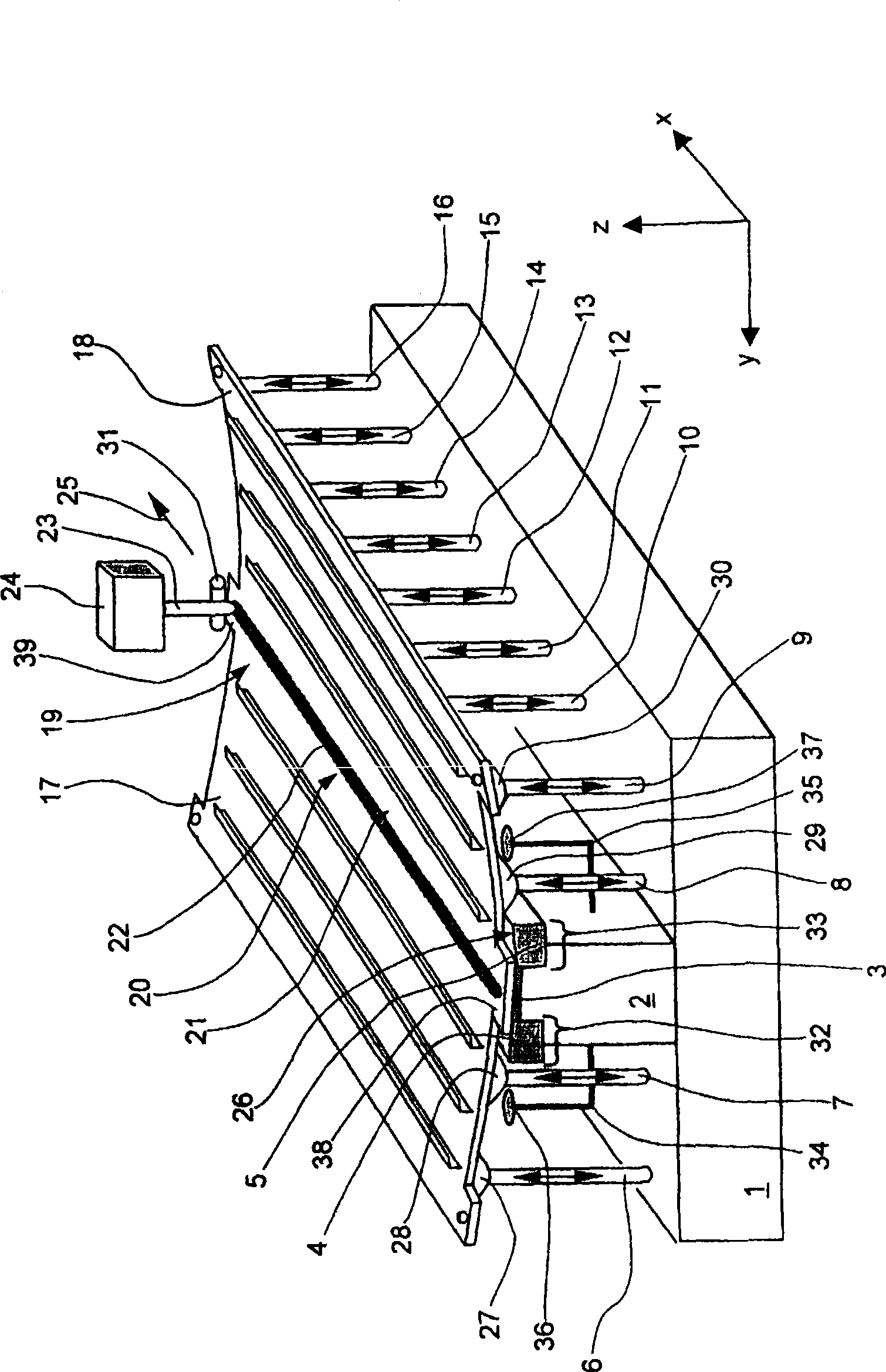
[0030] figure 1 Shows a perspective view of an exemplary embodiment of the apparatus of the invention for gripping two parts which are to be joined to each other by friction stir welding.

[0031] The device according to the invention comprises, among other elements, a base plate 1 , a base 2 , a solder substrate 3 and holding means 4 , 5 . A plurality of support elements are provided on both sides of the base. The support elements are preferably arranged evenly spaced from each other in a matrix. Such as figure 1 As shown, only half of the support elements 6 to 16 are shown here in order to enhance the graphic representation.

[0032] The first part 17 and the second part 18 are placed on the holding devices 4 , 5 and on the support elements 6 to 16 . The part can be a sheet metal or also a more complex part, such as a part of a fuselage shell or the like.

[0033] The components 17 , 18 are connected in the seam forming region 19 along the component edges 20 , 21 by a w...


PUM


Abstract

The invention relates to a method for clamping at least two parts (17, 18), especially aircraft parts (17, 18), to connect said parts by a weld (22) formed by friction stir welding between the edges of the two parts (17, 18) equipment. The individual components (17, 18) are received by a plurality of support elements (6-16) and a welded substrate (3) is provided beneath the weld (22). On both sides of the solder substrate (3) there is at least one holding device (4, 5) which can be filled with negative pressure to clamp the components (17, 18). The holding means (4, 5) which can be charged with negative pressure can allow the parts (17, 18) to be quickly and simply clamped for joining by the known friction stir welding process. By exchanging a small number of components, especially the holding devices (4, 5) and / or the soldering substrate (3), the device according to the invention can be adapted in a simple and flexible manner to several components with different geometries and / or dimensions ( 17, 18). The friction stir welding process can be carried out by clamping multiple types of parts, in particular all the above-mentioned parts (17, 18) with primary and / or secondary bends, by the same device. The device can be used for raw parts, such as sheet metal or the like, as well as for clamping and welding complex prefabricated individual parts, such as complete fuselage shells or partial shells. In addition, the apparatus of the present invention also enables friction stir welding, since heat loss in the seam forming zone (19) can be minimized by using low thermal conductivity materials for the holding means (4, 5) and / or the base (2). Has a higher propulsion rate.

Description

technical field [0001] The invention relates to a device for clamping at least two components, in particular aircraft components, to join said components by a weld seam formed by friction stir welding between the edges of the two components, wherein said components each consist of a plurality of support elements Received, and a welded substrate is provided beneath the weld. Background technique [0002] Known apparatus for holding parts for friction stir welding comprise a large, generally horizontal base on which the parts to be welded are supported. During the welding process, the components are held mechanically by large fixtures. The fixture must be designed to remain fairly stable based on the high mechanical forces generated during friction stir welding. Such clamping can be realized by threaded clamps or hydraulically actuatable clamps. [0003] In both cases, it is initially necessary to provide high construction costs. In addition, mechanical clamps limit the si...

Claims


Application Information

Patent Timeline
Patent Type & Authority Patents(China)
IPC IPC(8): B23K37/04B25B11/00
CPCB23K20/126B25B11/005B23K37/0443
Inventor 达妮埃拉·洛瓦塞尔
Owner AIRBUS OPERATIONS GMBH
Learn More