
Double airbag trachea cannula

A technology of tracheal cannula and double airbag, applied in the field of medical devices, can solve the problems of tracheal stenosis, erosion, mucosal ischemia and the like

Inactive Publication Date: 2009-06-24
SECOND MILITARY MEDICAL UNIV OF THE PEOPLES LIBERATION ARMY
View PDF4 Cites 0 Cited by
  • Summary
  • Abstract
  • Description
  • Claims
  • Application Information

AI Technical Summary

Problems solved by technology

[0003] However, the above-mentioned tracheal tube has the following disadvantages: 1. The outer tube only has one air bag, and the long-term compression of the air bag on the tracheal wall is prone to mucosal ischemia, erosion, necrosis or granuloma and then causes symptoms such as tracheal stenosis. In 1969, Cooper and Grillo confirmed that only 48 hours after the balloon inflation of the tracheal tube, the tracheal mucosa was ulcerated. In 1984, Wited confirmed that the occurrence of tracheal stenosis was related to the length of intubation time. Among patients who were intubated for more than 11 days, 12% developed gas The airway is narrow, and the usual time of use is 2 to 3 weeks, so the incidence of the above-mentioned symptoms is relatively high; 2. The airbag is inflated by a syringe, and the amount of inflation is difficult to control. If the airbag is inflated too much, the pressure of the airbag is too high to compress the tracheal wall, which will easily cause mucosal defect. Blood, erosion, necrosis; air leakage occurs during mechanical ventilation if the air bag pressure is too low

Method used


Image

  • Double airbag trachea cannula
  • Double airbag trachea cannula
  • Double airbag trachea cannula

Examples


Embodiment 1

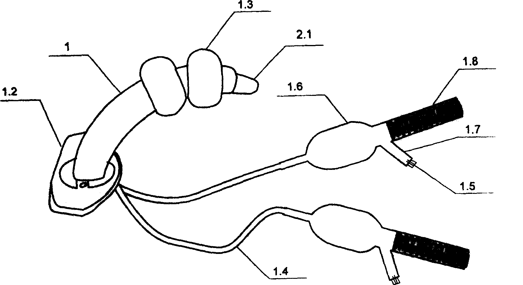
[0018] The present invention comprises two parts, an outer tube 1 and a tube core 2. The outer tube 1.1 of the outer tube is bent in a 120° arc, with a length of 90mm (inner arc 78mm, outer arc 102mm), outer diameter 11.9mm, inner diameter 8mm, and the outer diameter of the airbag after inflation. The diameter is 32mm, the width on both sides is 15mm, and the distance between the two airbags is 5mm. The inflatable indicator balloon is 1.6Φ30mm, and the length of the inflation tube 1.4 is 300mm.

[0019] The head 2.1 of the tube core 2 is conical, the top is blunt, the tail end 2.2 is a square sheet, the length of the tube body 2.3 in the middle matches the sleeve 1.1, the tube core 2 is placed in the outer sleeve, and the head of the tube core 2.1 just extends out of the distal nozzle 1.1.1 of the casing 1.1, and the tube core tail end 2.2 just covers the proximal nozzle 1.1.2 of the casing 1.1.

Embodiment 2

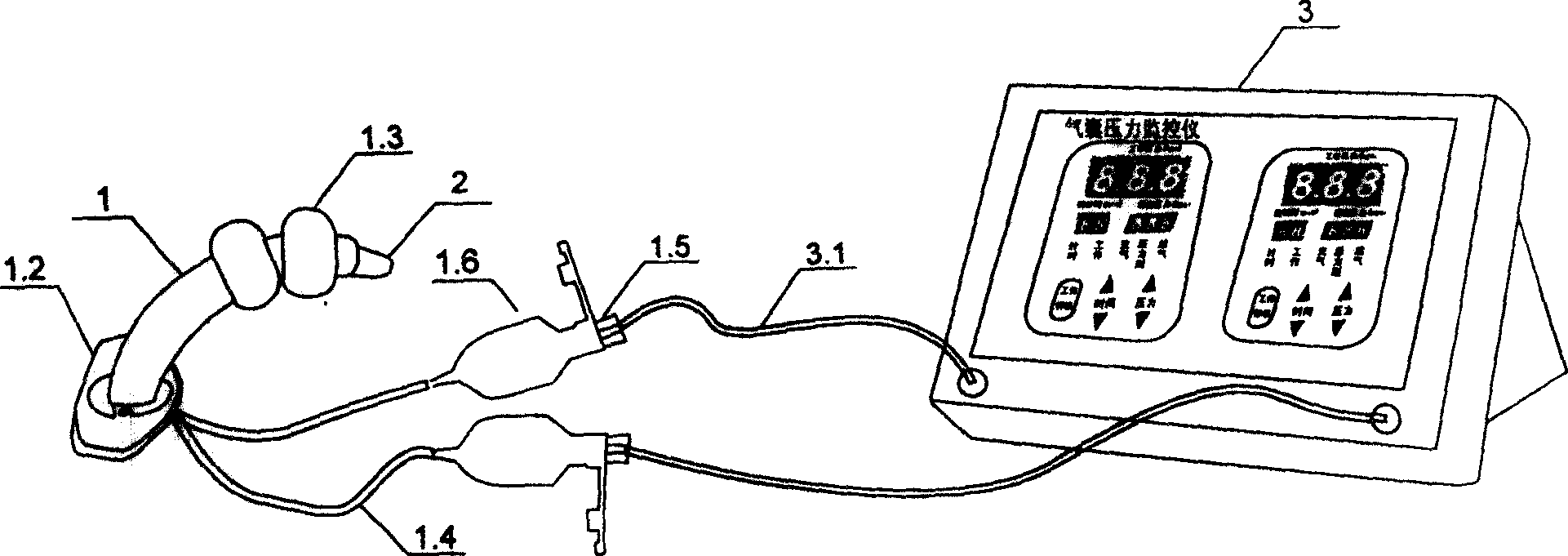
[0021] The inflation valve 1.5 at the air pressure indicating balloon 1.6 end of the present invention is connected with the numerically controlled air bag pressure monitor 3, and all the other are the same as embodiment 1, such as figure 1 shown.

Embodiment 3

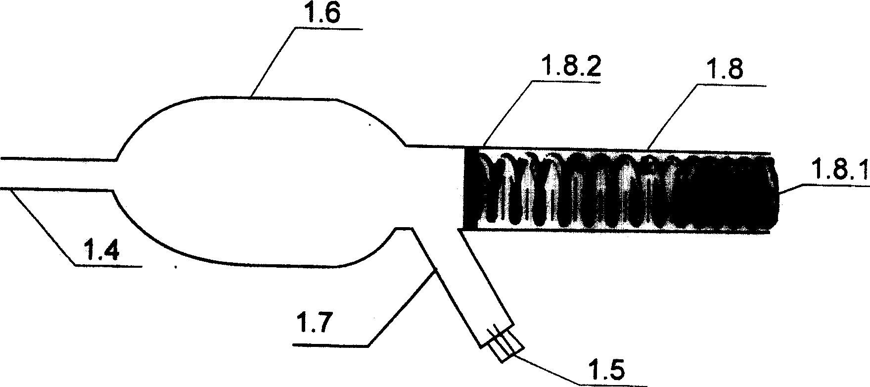
[0022] Embodiment 3. The air pressure indicating balloon 1.6 tail of the present invention is bifurcated into two branch pipes, one branch pipe is provided with the inflation valve pipe 1.7 of the inflation valve 1.5 at the mouth of the pipe, and the other branch pipe is the air bag pressure indicator 1.8 (length 4cm, outer diameter 4mm, inner diameter 3.8mm), the pressure scale (0~30mmHg) is marked on the tube wall of the airbag pressure indicator, and there is a metal spring 1.8. The circular rubber valve 1.8.2 of mm links to each other, and the diameter of this circular rubber valve matches the cavity diameter of the airbag pressure indicator to prevent gas from overflowing, and all the other are the same as embodiment 1, such as figure 2 shown.


PUM


Abstract

The invention relates to the technical field of medical instruments, and relates to a pressure monitoring double-airbag tracheal tube. The present invention changes the existing single-balloon tracheal tube into a double-balloon tracheal tube. After the air bag is inflated, the gap between the tracheal tube and the inner wall of the trachea is closed and the air bags are used alternately to shorten the compression time of the air bag on the local tracheal mucosa, thereby It can prevent or reduce complications such as tracheal mucosal ischemia, erosion, necrosis or tracheal stenosis caused by long-term pressure on the inner wall of the trachea. In order to monitor and adjust the gas pressure in the airbag in time, a pressure monitoring device can be installed, such as connecting the inflation valve with a numerically controlled airbag pressure monitor, or bifurcating the tail of the air pressure indicating balloon into two branch pipes, one of which is the inflation valve pipe, The other is the airbag pressure display tube, which can dynamically monitor the pressure in the double airbags at any time, so that the operator can make timely pressure adjustments and keep the airbag pressure constant.

Description

technical field [0001] The invention relates to the technical field of medical devices, and relates to a double-balloon tracheal tube. Background technique [0002] Clinically, patients undergoing tracheotomy often need to be placed with a tracheal tube to keep the airway open. Existing tracheal tubes include two parts, an outer tube and a tube core. Wherein the outer casing is composed of a casing, an indicating balloon, an inflation tube, an inflation valve, a fixed wing, and an air bag. The fixed wing is located on the outer wall of the proximal end of the cannula, and the air bag is located on the outer wall of the far end of the cannula. One end of the inflatable tube passes through the connection between the fixed wing and the cannula, extends along the tube wall of the cannula and is connected with the air bag, and the other end of the inflatable tube For indicator balloon and inflation valve. The tube core is composed of head, tail and tube body. The head is conic...

Claims


Application Information

Patent Timeline
Patent Type & Authority Patents(China)
IPC IPC(8): A61M16/00A61M16/04A61M39/00
Inventor 卢根娣席淑华周立陶红赵耀忠
Owner SECOND MILITARY MEDICAL UNIV OF THE PEOPLES LIBERATION ARMY
Learn More