Image forming apparatus

An image and equipment technology, applied in the field of electrophotography or electrostatic recording system, can solve the problems of reducing productivity and elapsed time, and achieve the effect of improving productivity

Inactive Publication Date: 2009-06-10
CANON KK
View PDF5 Cites 0 Cited by
  • Summary
  • Abstract
  • Description
  • Claims
  • Application Information

AI Technical Summary

Problems solved by technology

This causes considerable time to elapse in the pre-rotation stage between the start of the operation and the formation of the first image on the transfer material 20, thereby reducing productivity.

Method used


Image

  • Image forming apparatus
  • Image forming apparatus
  • Image forming apparatus

Examples


no. 1 example

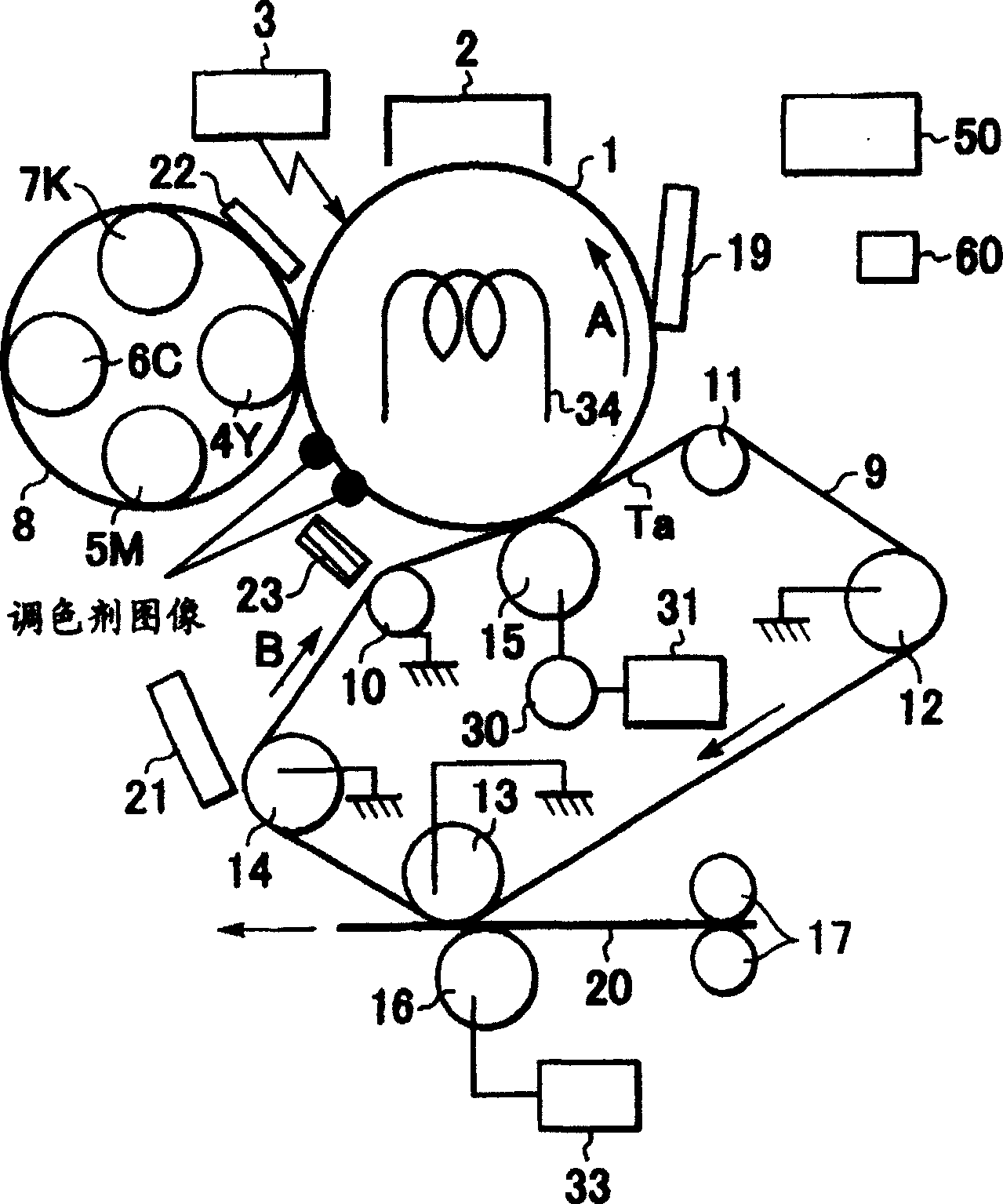
[0047] figure 1 is a schematic block diagram of a color image forming apparatus according to an embodiment of the present invention.

[0048] exist figure 1 , a photosensitive drum 1 (the photosensitive drum 1 being a drum-shaped electrophotographic photoconductor serving as an image carrier) rotates in an arrow A direction. On its surface, an electrostatic latent image is formed by a known electrophotographic process. A charging device or charger 2 is arranged along the rotational direction of the photosensitive drum and an exposure unit 3 or image forming device partially exposes the toner image on the photosensitive drum. Toner colors using Y, M, C, and K colors are used for color images. A yellow (Y) developed image (toner image) is formed from the electrostatic latent image by the developer device 4Y mounted on the rotary developing unit 8 . Under the rotation of the photosensitive drum 1 , the toner image is mainly transferred onto the intermediate transfer belt 9 ...

no. 2 example

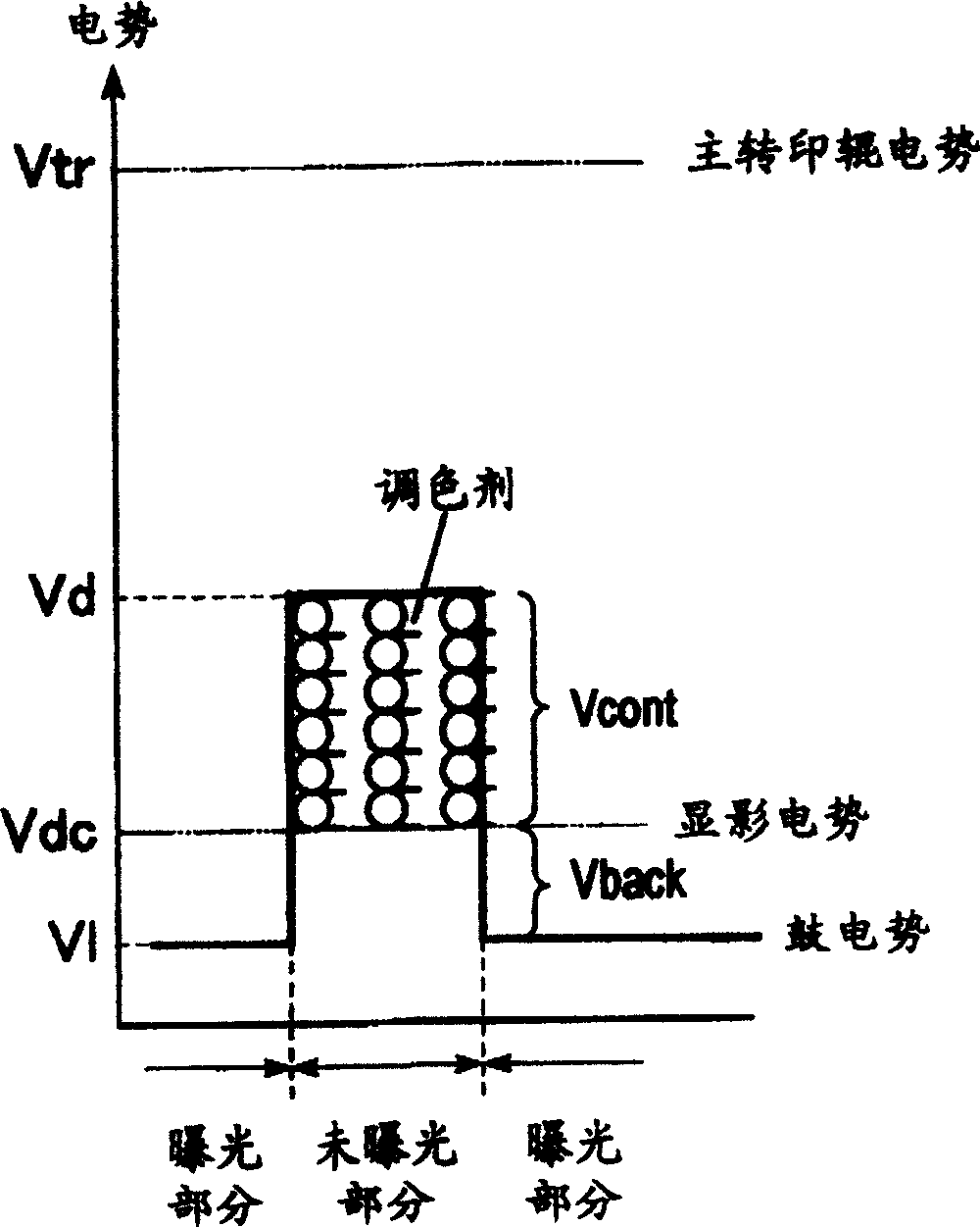
[0080] As in the case of the first embodiment, in the second embodiment, the toners used are all of the negatively charged type, and of the type that makes the photosensitive drum 1 positively charged. Such as figure 2 As shown in , the developing operation is performed by the normal developing method.

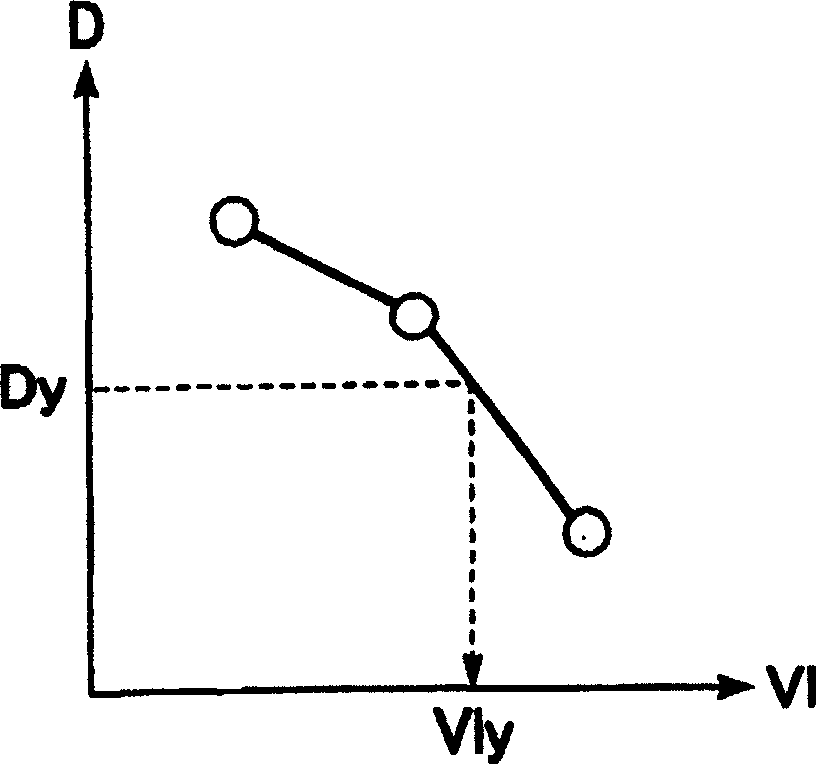
[0081] This embodiment differs from the first embodiment only in that temperature and humidity information is used in this embodiment when determining the V1 value for each color.

[0082] While the potential detector 22 monitors the surface potential of the photosensitive drum 1, first, the photosensitive drum 1 is uniformly charged to the drum potential Vd by the charger 2, a toner image is developed at this potential, and the exposure unit 3 makes the photosensitive drum without adjustment. The developed area of ​​the toner image is exposed and destaticized to potential V1.

[0083] Such as figure 1 As shown in , in this case, when the developer device 4Y is moved and ...


PUM


Abstract

A system and method for determining, during a pre-rotation period, a proper transfer bias for colors, e.g. YMCK. These proper transfer bias voltages are applied to a primary transfer roller, which enables proper transfer of color images from a photoconductive drum. Four exposure bias voltages for each of YMCK are determined. The first exposure bias voltage for Y is applied to the photoconductive drum, while three predetermined voltages are applied to a primary transfer roller in order to obtain corresponding currents and a voltage / current relationship thereof, from which a proper transfer bias voltage for Y is determined. For all subsequent colors, a proper transfer bias voltage for each subsequent color is determined by employing the Y exposure bias voltage and the exposure bias voltage for each the subsequent colors, MCK. In an exemplary embodiment, it is noted that the proper transfer voltages are obtained during pre-rotation in which the primary transfer roller rotates no more than three times.

Description

technical field [0001] The present invention relates to an electrophotographic or electrostatic recording system, and more particularly, the present invention relates to a method for transferring a developed image from an image carrier to a transfer material or intermediate transfer member. Background technique [0002] Such as Figure 5 As shown in , a conventional image electrophotographic system such as a copier or a laser printer generally includes an electrophotographic photoconductor (photosensitive drum) 1 which is an image carrier, and a charger 2 for charging the photosensitive drum 1 . Other components of the conventional electrophotographic system include an exposure unit 3 and developing devices 4Y, 5M, 6C, and 7K for yellow (Y), magenta (M), cyan (C), and black (BK) color components, respectively. Each of these developing devices contains a magnetic material called developer, which is used to carry toner. [0003] Such as Figure 5 As shown in , the system ope...

Claims


Application Information

Patent Timeline
Patent Type & Authority Patents(China)
IPC IPC(8): G03G15/16G03G15/01
CPCG03G2215/0177G03G15/0131
Inventor 高柳浩基
Owner CANON KK
Why Eureka
Try Eureka