Combined lock floor joist
A combination and keel technology, applied in the direction of floor, building components, covering/lining, etc., can solve the problems of easily damaged house structure, large stress of wooden floor, deformation of wooden floor, etc., to improve installation quality, fast installation and easy installation convenient effect
- Summary
- Abstract
- Description
- Claims
- Application Information
AI Technical Summary
Problems solved by technology
Method used
Image
Examples
Embodiment 1
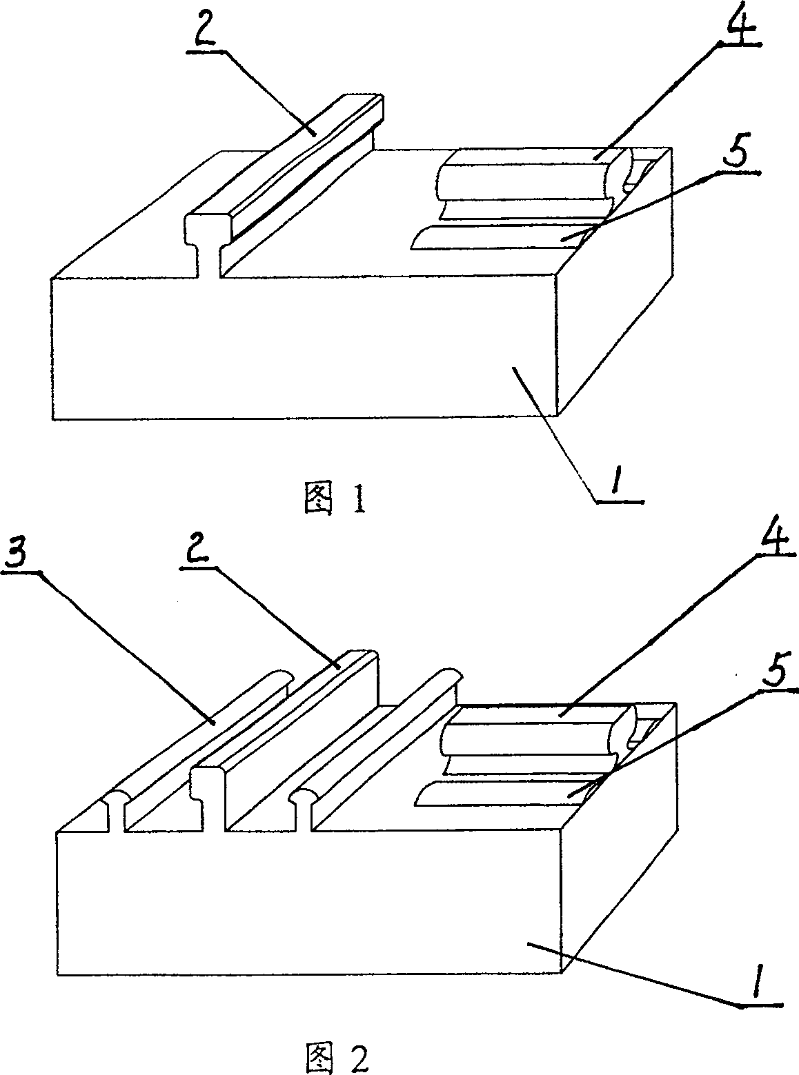
[0019] Embodiment 1: Refer to Fig. 1 and Fig. 4 . The keel 1 of the present invention is rectangular, on one side of the surface of the keel 1 there is a longitudinal main rib 2 with a T-shaped cross-section; 4. On the surface of the keel on both sides of the transverse main rib 4, at least one, or two or more transverse auxiliary ribs 5 parallel to the transverse main rib 4 may be arranged on each side.
[0020] In this embodiment, the transverse main ribs 4 and the transverse auxiliary ribs 5 are arranged side by side and have the same length. The cross section of the lateral auxiliary rib 5 is a raised boss, and the surface of the raised boss is arc-shaped.
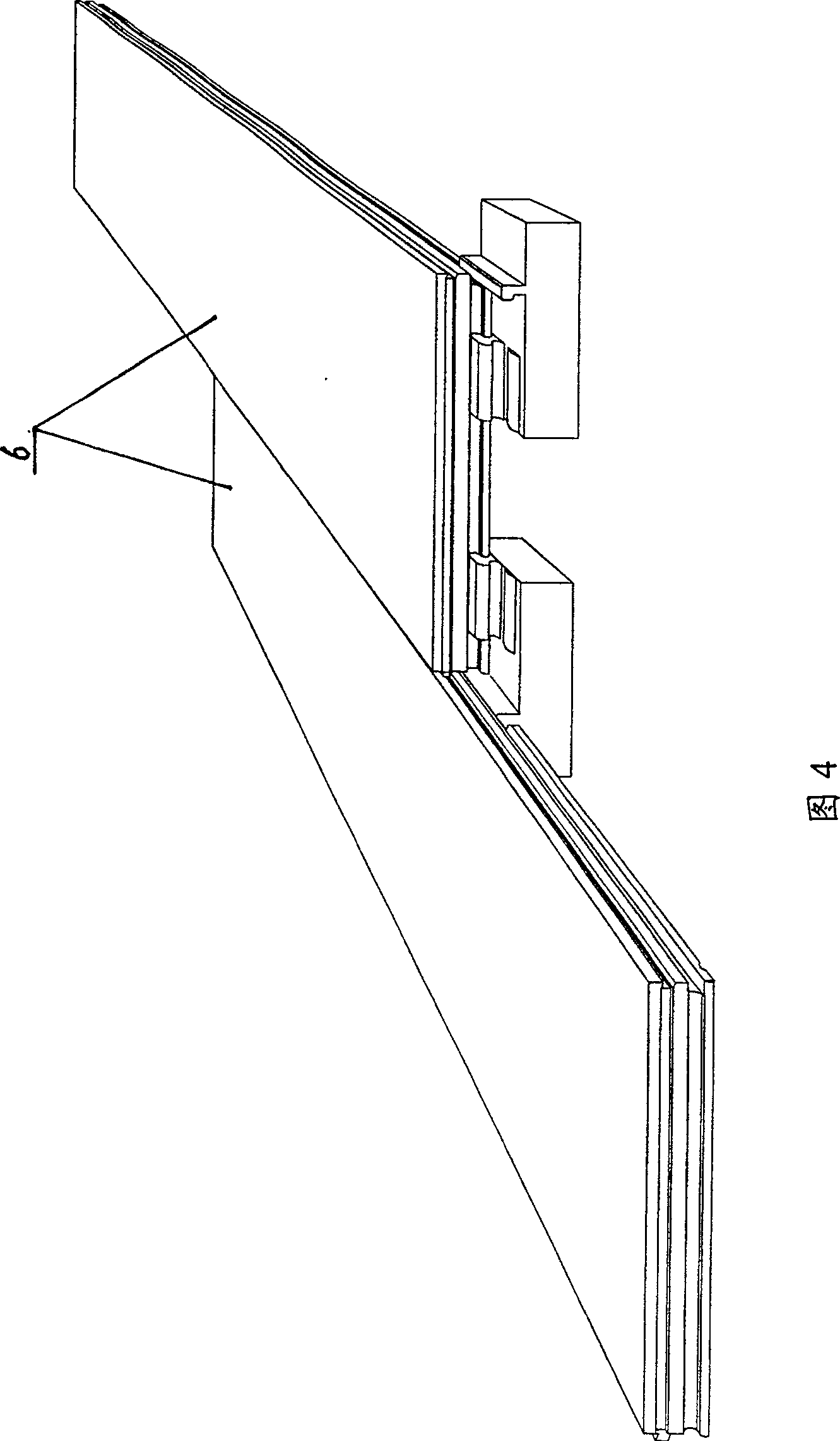
[0021] The present embodiment is installed at the joint of three boards, as shown in Figure 4. When installing, first splice the transverse seams between two adjacent plates 6, insert the transverse main ribs 4 and transverse auxiliary ribs 5 in the keel 1 into the corresponding grooves of the plates 6, and then inse...
Embodiment 2
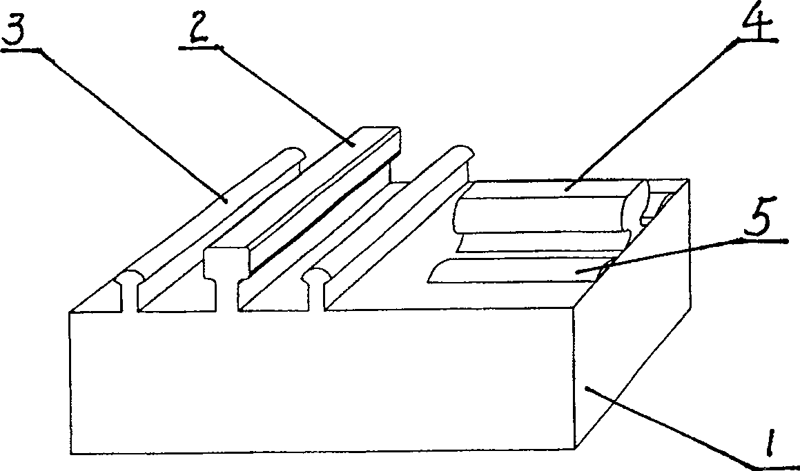
[0022] Embodiment 2: Refer to Fig. 2 and Fig. 5 . The keel 1 described in this embodiment is rectangular, and a longitudinal main rib 2 with a Γ-shaped cross section is provided on one side of the surface of the keel 1. On the keel surface on both sides of the longitudinal main rib 2, one is arranged on each side, and two can also be arranged. Or a plurality of longitudinal auxiliary ribs 3 parallel to the longitudinal main ribs 2; on the other side of the keel surface, a transverse main rib 4 with a T-shaped cross-section perpendicular to the above-mentioned longitudinal main ribs 2 and longitudinal auxiliary ribs 3 is provided, and two sides of the transverse main ribs 4 On the surface of the side keel, each side is provided with one or two or more transverse auxiliary ribs 5 parallel to the transverse main ribs 4 .
[0023] In this embodiment, the longitudinal main ribs 2 and the longitudinal auxiliary ribs 3 are arranged side by side and have the same length; the transvers...
Embodiment 3
[0025] Embodiment 3: refer to image 3 and Figure 6. The structure and usage method of this embodiment are basically the same as those of Embodiment 2, except that the cross-section of the longitudinal main rib 2 of this embodiment is T-shaped.
[0026] In the above embodiments, nail holes for fixing the keel can be provided in the vertical direction of the keel 1 so that the keel can be nailed to the ground, wall or top surface. The keel 1 can be set in different thickness series to facilitate the adjustment of the floor height. The cross-sections of the longitudinal auxiliary ribs 3 and the transverse auxiliary ribs 5 can be T-shaped, Γ-shaped, rectangular, triangular, arc-shaped, polygonal, etc., or raised bosses whose surface is arc-shaped. It can be set on one side of the main reinforcement, or on both sides, or not. Which one to use depends on the installation position of the plate.
PUM
 Abstract
Description
Claims
Application Information
 - R&D
- Intellectual Property
- Life Sciences
- Materials
- Tech Scout
- Unparalleled Data Quality
- Higher Quality Content
- 60% Fewer Hallucinations
Browse by: Latest US Patents, China's latest patents, Technical Efficacy Thesaurus, Application Domain, Technology Topic, Popular Technical Reports.
© 2025 PatSnap. All rights reserved.Legal|Privacy policy|Modern Slavery Act Transparency Statement|Sitemap|About US| Contact US: help@patsnap.com


