Eureka AIR delivers breakthrough ideas for toughest innovation challenges, trusted by R&D personnel around the world.

Transmission line for cross groove structure

A transmission line and cross-slot technology, which is applied in the field of transmission lines, can solve the problems of increasing manufacturing costs, increasing capacitor wiring space, and reducing

Inactive Publication Date: 2009-06-03
INVENTEC CORP
View PDF4 Cites 0 Cited by
  • Summary
  • Abstract
  • Description
  • Claims
  • Application Information

AI Technical Summary

Problems solved by technology

However, although this existing technology can solve the problem of signal reflection, it increases the manufacturing cost and must face the problem of reducing the wiring space due to the increase of capacitance

Method used


Image

  • Transmission line for cross groove structure
  • Transmission line for cross groove structure
  • Transmission line for cross groove structure

Examples


Embodiment Construction

[0034] The detailed features and advantages of the present invention are described in detail below in the embodiments, the content of which is sufficient to enable any person familiar with the relevant art to understand the technical content of the present invention and implement it accordingly, and according to the content disclosed in this specification, the scope of the patent application and the drawings , anyone skilled in the relevant art can easily understand the related objects and advantages of the present invention.

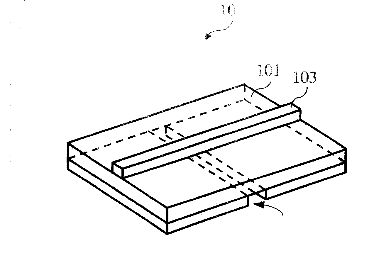
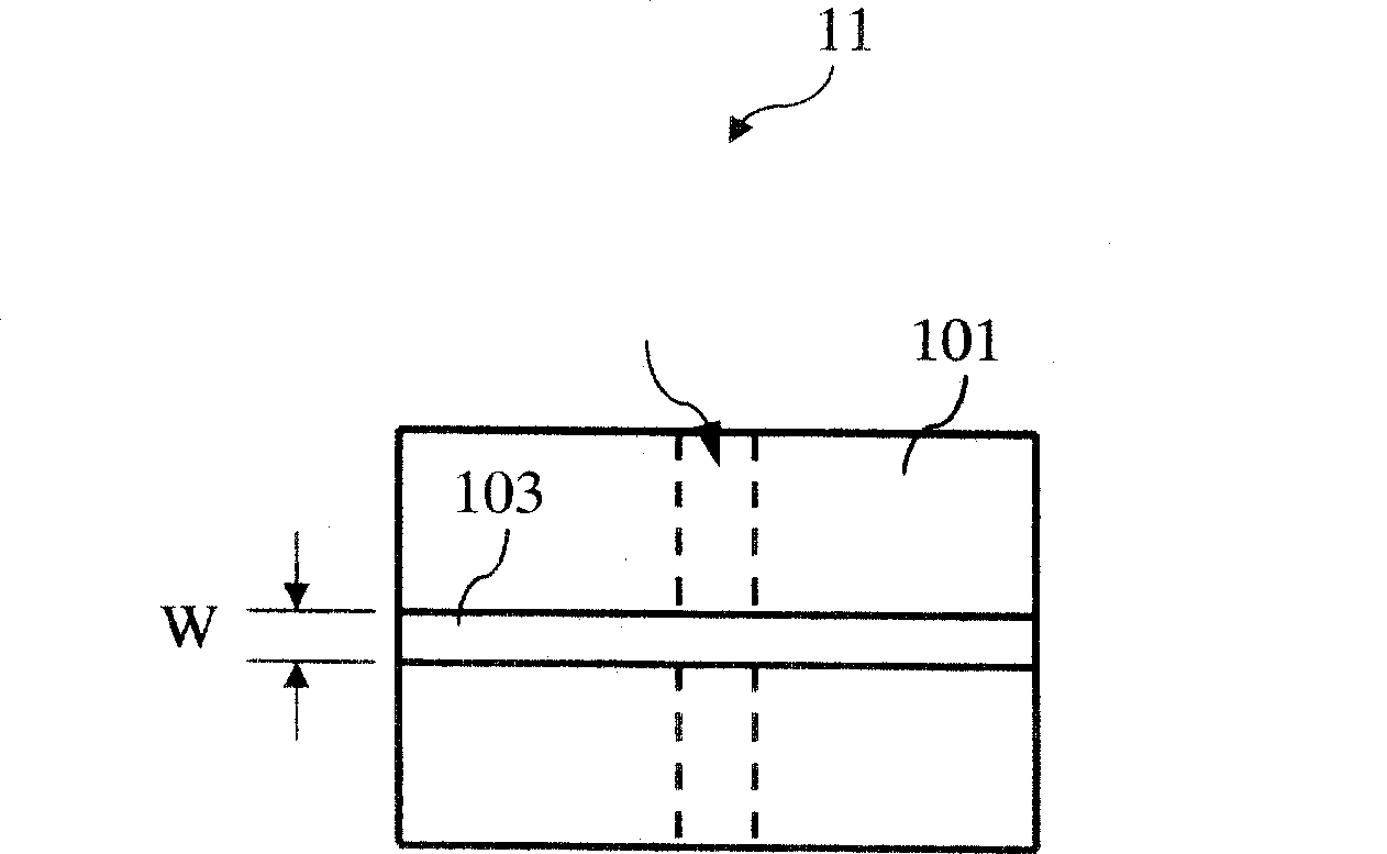
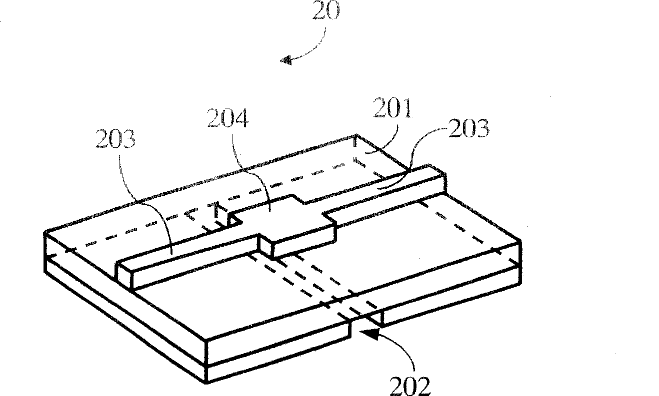
[0035] The present invention uses the concept of impedance matching to change the width of the transmission line so that part of the line segment of the transmission line across the groove of the printed circuit board presents capacitive low-impedance characteristics to achieve impedance matching at the design frequency point, thereby improving the performance of the transmission line. The effect of impedance discontinuity caused by the high impedance ch...


PUM


Abstract

A design of transmission line used in cross-trench structure, taking use of the conception of impedance matching, optimizes the length and width of part of the transmission line which connects to the cross-trench structure. Thus the part of transmission line shows low-impedance characteristic as a capacitor, and accomplishes the impedance matching at designed frequency points, which will improve the discontinuous effect caused by the high-impedance characteristic of the transmission line on cross-trench structure.

Description

technical field [0001] The present invention relates to a transmission line, in particular to a transmission line used in a cross-slot structure. Background technique [0002] Wiring (Layout) is one of the designs of a Printed Circuit Board (PCB). The quality of wiring will directly affect the performance of the entire system, and most high-speed circuit design theories will eventually be realized and verified through wiring. It can be seen that wiring is crucial in high-speed printed circuit board design. [0003] In the design of multilayer printed circuit boards, in order to save costs, fewer layers must be used to complete the wiring of the entire board. Therefore, different voltage levels must be cut on the limited power supply layer. In this way, If the transmission line crosses these different voltage cutting planes, an Oversplit Plane structure is formed. [0004] Please refer to Figure 1A and Figure 1B , Figure 1A is a schematic diagram 10 of an existing trans...

Claims


Application Information

Patent Timeline
Patent Type & Authority Patents(China)
IPC IPC(8): H05K1/02H05K1/00G06F17/50
Inventor 杨志明陈彦豪
Owner INVENTEC CORP
Why Eureka
Eureka Blog
Learn More