Speed regulator for electric vehicle
A speed governor and electric vehicle technology, which is applied to electric vehicles, motor vehicles, motorcycles, etc., can solve the problems of single fixed mode and hinged mode, limited functions and scope of use, etc., and achieve reliable and improved hinged and fixed modes. Fixed method and operation method, effect of cost reduction
- Summary
- Abstract
- Description
- Claims
- Application Information
AI Technical Summary
Problems solved by technology
Method used
Image
Examples
Embodiment 1
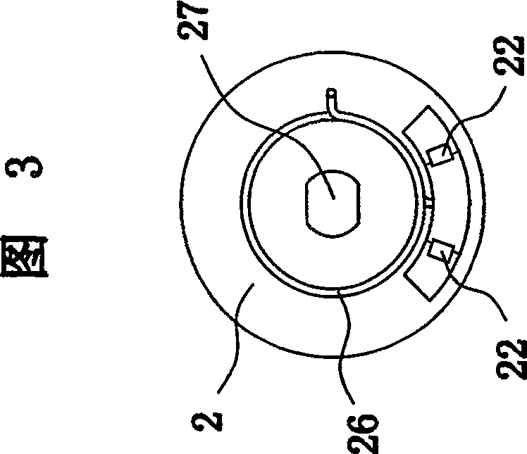
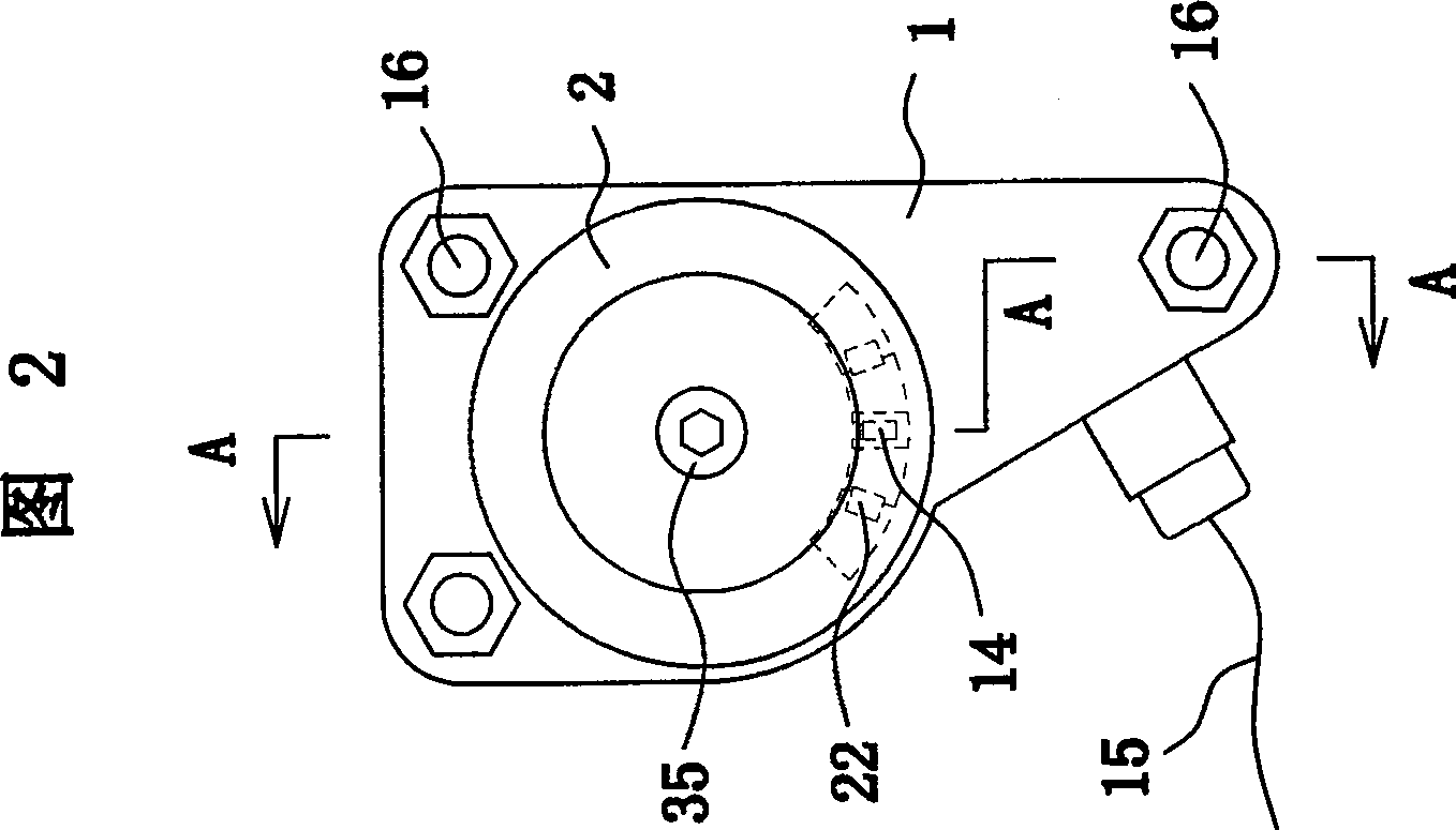
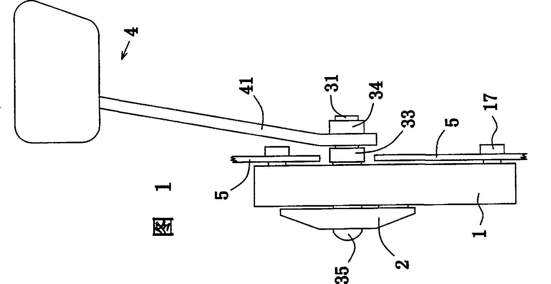
[0028] Preferred embodiment 1: refer to Fig. 1-4. An electric vehicle governor, comprising a handle 1 with a through hole and a handle 2 with a flat hole 27, the seat handle 1 is provided with an induction probe 14, and the handle 2 is provided with a pair of magnets 22, and the magnets 22 extend into the and cooperate with the induction probe 14 in the seat handle. The inner and outer sides of the seat handle 1 are planes, and three installation holes 16 are arranged on it, and the installation holes are hexagonal stepped holes at the inner end. The induction probe 14 on 1 is electrically connected to the controller through the lead wire 15 .
[0029] The speed governor of the present invention also includes a speed governor shaft 3 . Referring to Fig. 4 and Fig. 9, the shaft 3 includes shaft heads 31, 31' with flat positions, a journal 32 and a collar 33. The width of the journal 32 is greater than the width of the seat handle 1 by more than 0.1 mm, and the diameter of th...
Embodiment 2
[0031] Preferred embodiment 2: see Figure 5. The seat handle 1 and the turning handle 2 of this example are basically the same as the example 1, the difference is that in this example, bearings 18 and 18 are added on both sides of the through hole of the seat handle 1, and the specific solution is to set the bearings on both sides of the through hole of the seat handle 1 Seat and bearing 18,18 is installed in it. As shown in Figures 5 and 7, the shaft 3 of this example is also improved. The shaft 3 includes a journal 32, a collar 33 and a shaft head 31 with a flat position. The journal 32 passes through the bearings 18, 18 Hinged with the seat handle 1, the flat position of the shaft head 31 cooperates with the flat hole 27 and is provided with an external thread and an internal screw hole 37. The handle 2 is mounted on the shaft head 31 and fastened by a nut 34.
[0032] As shown in Figure 10, the speed regulating pedal 4 of this example is installed on the outside of the nu...
Embodiment 3
[0034] Preferred embodiment 3: refer to Fig. 6 and Fig. 8 . This example is an improved solution of Example 1. In this example, the inner side of the seat handle 1 is provided with an annular extension part 11, and the handlebar 2 is provided with an inner cavity that cooperates with the extension part 11, and the handlebar 2 is sleeved outside the extension part 11; The through hole both sides of 1 are provided with bearing seat and bearing 18,18 are installed in the seat. The shaft 3 in this example includes a journal 32, a collar 33 and a shaft head 31 with a flat position. The journal 32 and the seat handle 1 are hinged through bearings 18 and 18. The collar 33 is a garland with four inner ends. With hexagonal mounting holes 36. Like Example 1, the through hole on the handle 2 of this example is a flat hole 27 , the shaft head 31 fits with the flat hole 27 and is provided with an internal screw hole 37 , and the handle 2 is fixedly connected to the shaft head 31 by a fixi...
PUM
 Abstract
Description
Claims
Application Information
 - R&D Engineer
- R&D Manager
- IP Professional
- Industry Leading Data Capabilities
- Powerful AI technology
- Patent DNA Extraction
Browse by: Latest US Patents, China's latest patents, Technical Efficacy Thesaurus, Application Domain, Technology Topic, Popular Technical Reports.
© 2024 PatSnap. All rights reserved.Legal|Privacy policy|Modern Slavery Act Transparency Statement|Sitemap|About US| Contact US: help@patsnap.com


