Deodorizing method and apparatus, and a vacuum cleaner using same
A vacuum cleaner and electric technology, applied in the direction of vacuum cleaners, deodorization, suction filters, etc., can solve the problems of short contact time, user discomfort, and foul smell in the exhaust airflow of electric vacuum cleaners, and achieve odor reduction, convenient use, and deodorization Effect that a bad smell effect improves
- Summary
- Abstract
- Description
- Claims
- Application Information
AI Technical Summary
Problems solved by technology
Method used
Image
Examples
Embodiment 1
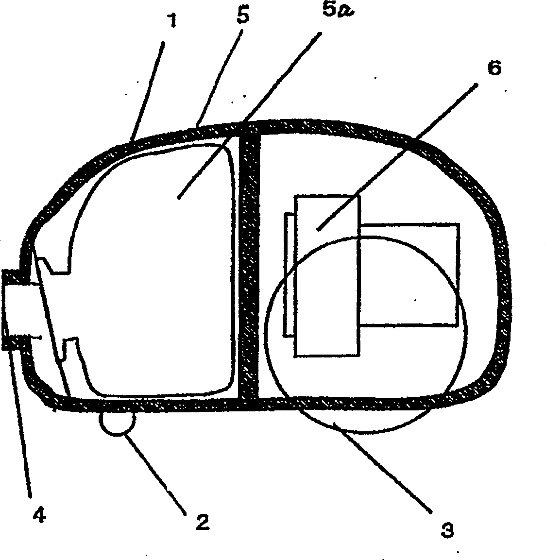
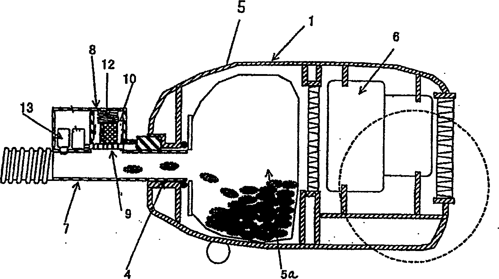
[0038] figure 1 It is a cross-sectional view showing a general structure of an electric vacuum cleaner. exist figure 1 Among them, a body 1 of the electric vacuum cleaner is provided with a front roller 2 and a pair of rear wheels 3 mounted on a pivot. The front portion of the body 1 is provided with an air suction port 4 for attracting dust. In addition, although it is not shown in the figure, the suction head for attracting dust is connected with the suction port 4 through an extension tube and a hose, continuously Perform dust suction operation. In addition, in the machine body 1 , a dust collection chamber 5 and an electric blower 6 are sequentially provided in the downstream direction of the dust suction port 4 .
[0039] The specific structure is as figure 2 As shown in , the body 1 of the electric vacuum cleaner is provided with a dust collection chamber 5 and an electric fan 6 for attracting dust. The dust collection chamber 5 is provided with a dust collection ba...
Embodiment 2
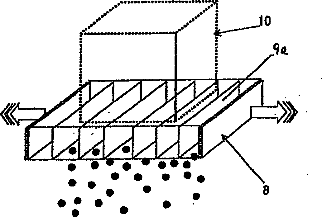
[0047] Figure 4 shows the second embodiment of the present invention. Here, for the same parts as those in the above-mentioned embodiment 1, repeated description thereof will be omitted, and only different parts will be described. In Embodiment 2, the pulverization / granulation device 9 is set in a movable state, and the deodorizing material 10 becomes granular or powdered with the movement of the pulverization / granulation device 9 . exist Figure 4 Among them, 11 is a drive device such as a vibrator for driving the pulverization / granulation device 9, and this drive device is controlled by a control unit 14 arranged at an appropriate position in the body of the vacuum cleaner. When the vacuum cleaner body 1 is connected to the power socket or the operation switch of the vacuum cleaner body 1 is turned on, the control unit 14 is energized. In addition, 12 in the figure is an elastic member such as a spring, which is used to press the deodorant material 10 on the pulverizatio...
Embodiment 3
[0055] Figure 5 Example 3 of the present invention is shown in . For the parts that are the same as those in Embodiments 1 and 2 above, repeated descriptions thereof will be omitted, and only different parts will be described. In Example 3, the pulverization / granulation device 9 is vibrated manually, and 16 is a manual operation part for realizing this purpose.
[0056] In this embodiment, when deodorization is required, the user only needs to grasp the operation part 16 to make the pulverization / granulation device 9 vibrate back and forth, so that the deodorant material 10 can be made into granular or powdery, so that it can be used at any Time to deodorize.
[0057] In addition, although the vibration driving mechanism of this pulverization / granulation device 9 is not shown in detail in the figure, it can be used to make the pulverization / granulation device 9 interlock with the electric wire reel of the power cord, and when the power cord is pulled The output and winding...
PUM
 Abstract
Description
Claims
Application Information
 - R&D
- Intellectual Property
- Life Sciences
- Materials
- Tech Scout
- Unparalleled Data Quality
- Higher Quality Content
- 60% Fewer Hallucinations
Browse by: Latest US Patents, China's latest patents, Technical Efficacy Thesaurus, Application Domain, Technology Topic, Popular Technical Reports.
© 2025 PatSnap. All rights reserved.Legal|Privacy policy|Modern Slavery Act Transparency Statement|Sitemap|About US| Contact US: help@patsnap.com


