
Clamp for grinding magnetic head, grinding apparatus and grinding method

A technology of a grinding device and a grinding method, applied in the directions of grinding devices, positioning devices, grinding machine tools, etc., can solve problems such as reducing the yield of finished products

Active Publication Date: 2009-05-06
SAE MAGNETICS (HK) LTD
View PDF7 Cites 0 Cited by
  • Summary
  • Abstract
  • Description
  • Claims
  • Application Information

AI Technical Summary

Problems solved by technology

It has been pointed out that one of the reasons is that the shape of the grinding surface of the strip actually needs to be similar to a high-order curve of more than 6 degrees in the length direction of the strip, and the traditional support method for the strip can only imitate at most Quadruple curve, which reduces yield (refer to Patent Document 3)

Method used


Image

  • Clamp for grinding magnetic head, grinding apparatus and grinding method
  • Clamp for grinding magnetic head, grinding apparatus and grinding method
  • Clamp for grinding magnetic head, grinding apparatus and grinding method

Examples


Embodiment Construction

[0066] Embodiments of the present invention will be described in detail below with reference to the accompanying drawings.

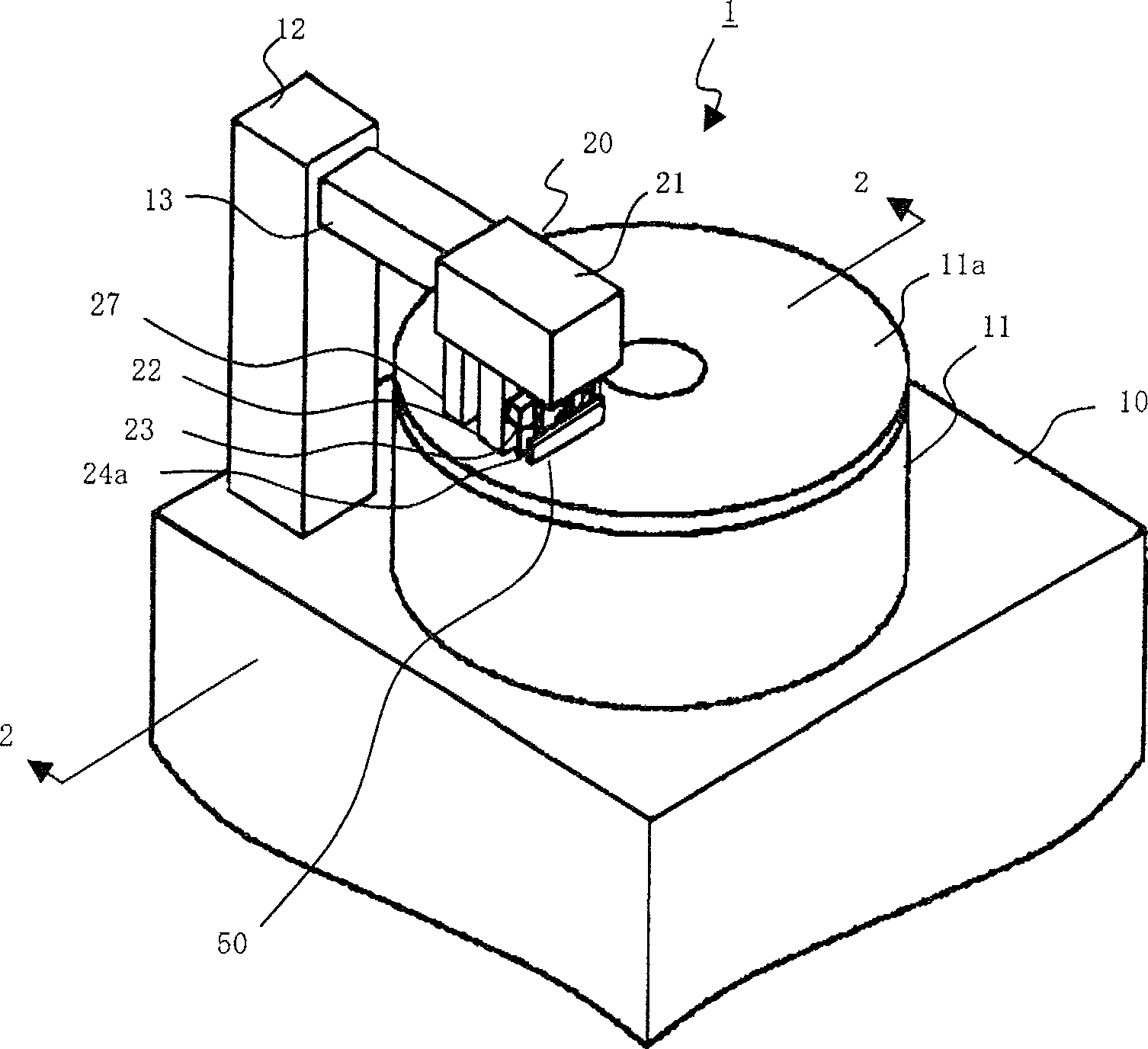
[0067] figure 1 A perspective view showing a schematic structure of a polishing apparatus according to an embodiment of the present invention. The grinding device 1 is used to grind the rod-shaped magnetic head members arranged in a row by the magnetic heads, that is, the elongated bar. Grinding device 1 comprises worktable 10, is located at the rotary grinding table 11 on the working table 10, is located at the pillar 12 of one side of rotary grinding table 11, the arm part 13 that stretches out from pillar 12 to the top of rotating grinding table 11 and installation. The component supporting part 20 of the arm part 13 . Wherein, the rotary grinding table 11 has a grinding surface 11a for grinding the elongated bar.

[0068] The component support part 20 includes a support part body 27 connected to the arm part 13, a part material 22 provided in fro...


PUM


Abstract

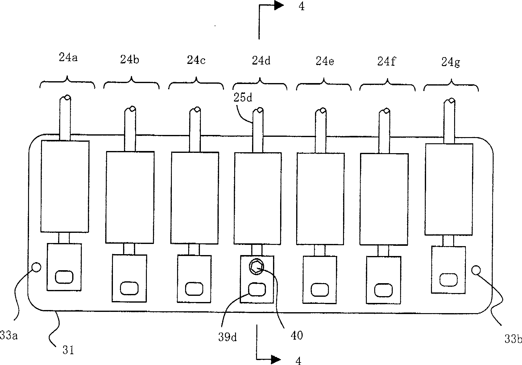
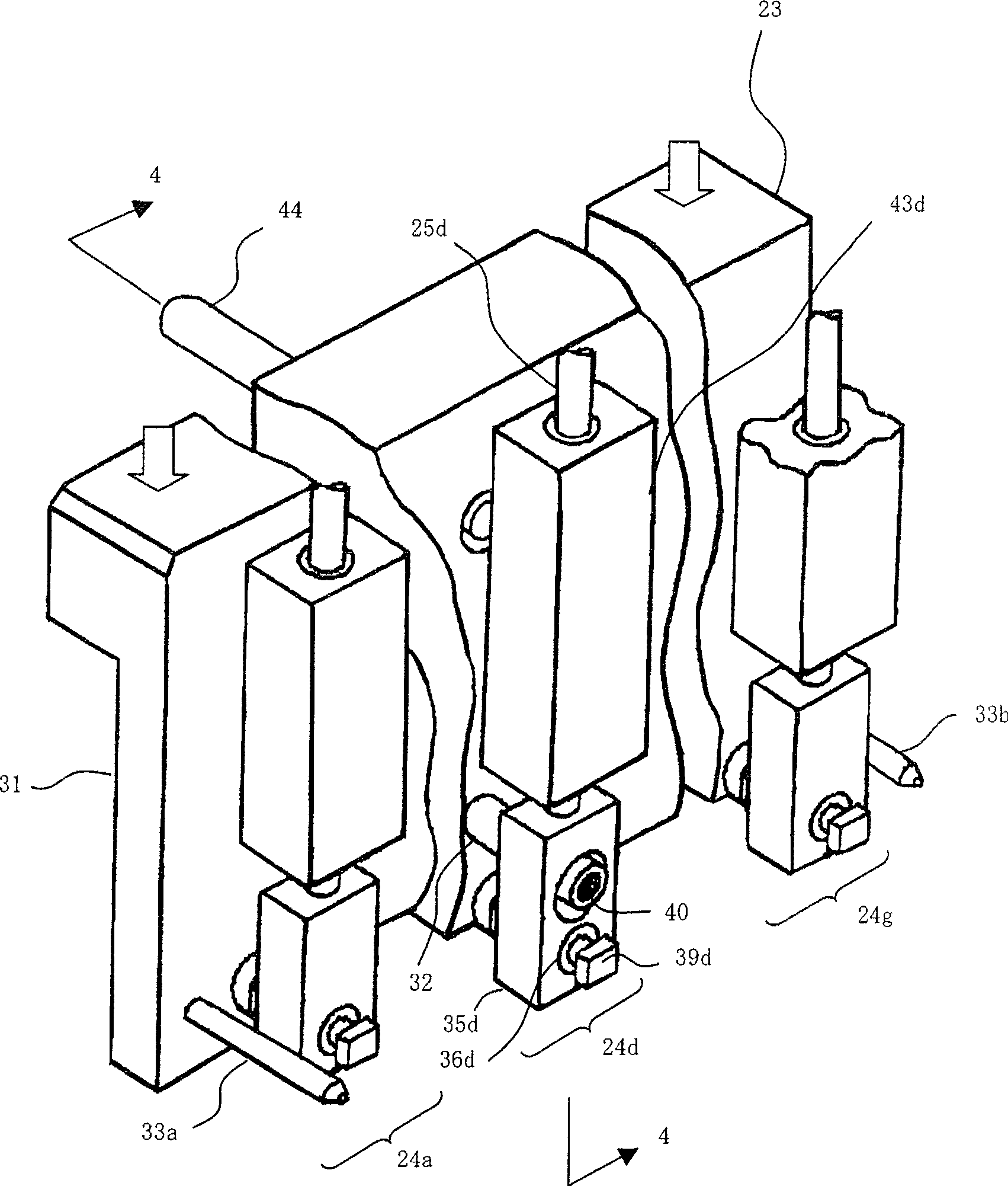
The invention discloses a milling holder which comprises: a holding part which makes the milled side of the milling object to the milling side of the miller, a body which fixes the milling holder on the miller, a plurality of load addition parts which are arranged on the length direction and at least receive the sequenced direction load of the milling side, a plurality of connecting parts which connect the holding part and the body part on the length direction and a plurality of lug parts which connect each load blending part and the holding part. It arranges at least one lug part between the adjacent connecting parts and the outer side of the two ends of the connecting part along the length direction.

Description

technical field [0001] The present invention relates to a kind of magnetic head manufacturing method with thin-film magnetic head, especially about the jig for polishing the magnetic head, the grinding device and the grinding flatness along the longitudinal direction of the elongated bar (bar) formed by a plurality of magnetic heads. method. Background technique [0002] Disk drives (disk drives), which are high-speed, large-capacity, high-reliability, and low-cost recording media, are widely used for recording digital information. After years of technological development, the recording density of magnetic disk drives has exceeded 100 Gbits / square inch. The magnetic disk drive is provided with a magnetic head (hereinafter referred to as a magnetic head) including a thin-film magnetic head for recording and reproducing information on a recording medium. The surface of the magnetic head facing the recording medium is called the air bearing surface (ABS). [0003] In an MR e...

Claims


Application Information

Patent Timeline
Patent Type & Authority Patents(China)
IPC IPC(8): B24B49/00B23Q3/06B23Q37/00
CPCG11B5/3169B24B37/30G11B5/3967G11B5/3163G11B5/3103B24B37/048G11B5/3173G11B5/3116
Inventor 藤井隆司保坂浩治李国伟洪晓明肖向彬
Owner SAE MAGNETICS (HK) LTD
Learn More