
Dismountable composition type piezolighter in high stability

A high-stability, combined technology, used in high-stability piezoelectric igniters, combined, and disassembled fields, can solve the problems of cracking, improving, and increasing the possibility of internal discharge, etc., to avoid cracking and ensure Effect of release efficiency and energy loss avoidance

Active Publication Date: 2009-04-22
FOSHAN YIQIANG ELECTRONICS
View PDF9 Cites 0 Cited by
  • Summary
  • Abstract
  • Description
  • Claims
  • Application Information

AI Technical Summary

Problems solved by technology

[0003] 1. After the glue is cured, the piezoelectric ceramics are glued to the inner cavity wall of the shell by the glue, which blocks the normal displacement of the piezoelectric ceramics after being hit and affects the voltage performance;
[0004] 2. After the piezoelectric ceramic is hit and vibrated, the cured glue wrapped around the piezoelectric ceramic is easy to peel off from it, resulting in a gap, easy breakdown between the two poles, and internal discharge phenomenon;
[0005] 3. The glue filling process is cumbersome. Since the glue will solidify, it needs to be vacuumed in time and stored at regular intervals. The layout of the production site is strict, which also affects the production cycle;
[0006] 4. For defective products due to improper glue filling process and other reasons, since the shell, piezoelectric ceramics, piezoelectric anvil, metal base, and pole pieces have been fixed into a whole, it is difficult to disassemble. This part cannot be recycled, only Can be scrapped;
[0007] 5. Filling glue from the electrode connection port, it is difficult to completely drain the air bubbles around the piezoelectric ceramics and other parts, increasing the possibility of internal discharge;
[0008] 6. Due to factors such as the tolerance of plastic parts and metal cap accessories, especially the installation method of the metal cap rotating and pressing, it is difficult to ensure the close connection between the bottom surface of the inner wall of the metal cap and the surface of the piezoelectric ceramic electrode, and a certain angle may be formed. Uneven stress on the surface of piezoelectric ceramics, prone to cracking
[0009] 7. The occurrence of the above-mentioned points 5 and 6 cannot be directly detected by naked eyes, which is not conducive to the improvement of the pass rate of products in the subsequent process.

Method used


Image

  • Dismountable composition type piezolighter in high stability
  • Dismountable composition type piezolighter in high stability
  • Dismountable composition type piezolighter in high stability

Examples


Embodiment 1

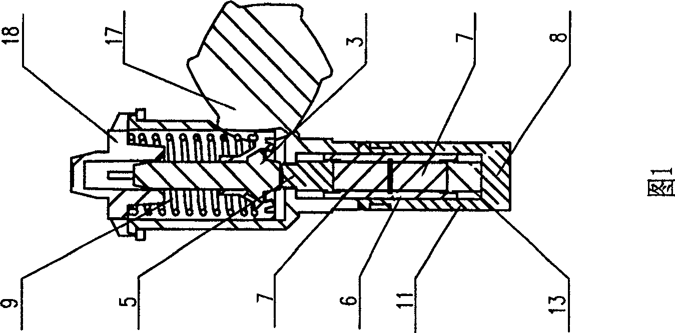
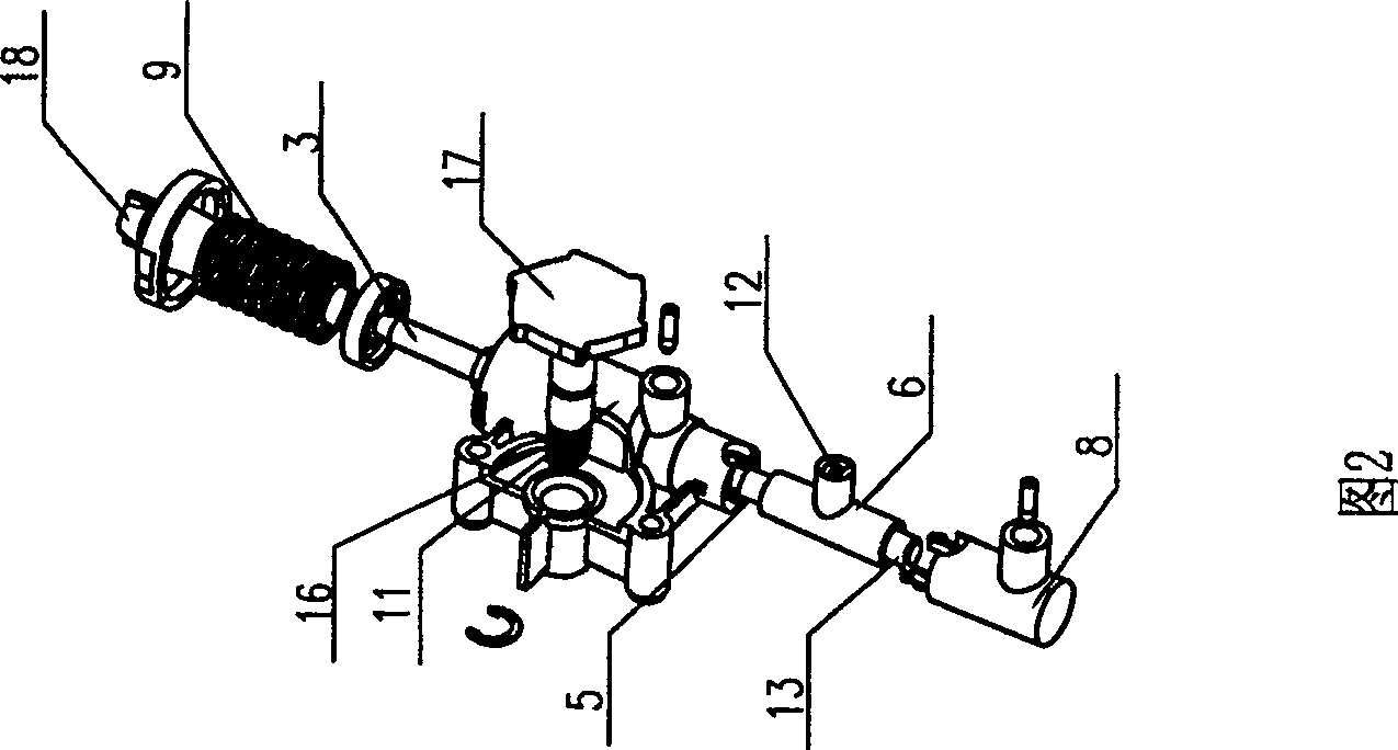
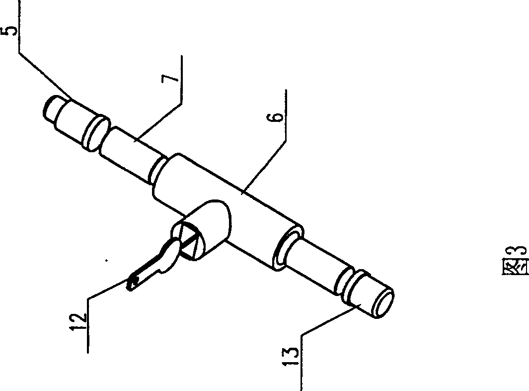
[0032] As shown in Figure 1, Figure 2 and Figure 3, the detachable combined high-stability piezoelectric igniter of the present invention includes a firing device, a housing 11, a base 8 and a piezoelectric anvil 5, a piezoelectric seat 13, a piezoelectric A piezoelectric ceramic assembly composed of electric ceramics 7, electrode sheets 12, and three-way body 6. The firing device is composed of a firing spring 9, a hammer 3 and a knob 16. A ratchet 17 is arranged at the bottom end of the knob 16 on the firing device. The ratchet 17 is clamped with the hammer 3, and the hammer 3 and the firing spring 9 on the firing device are packaged in the housing 11 through the end cover 18. The piezoelectric ceramic assembly is composed of a piezoelectric ceramic 7 and a piezoelectric anvil 5. And piezoelectric seat 13 is combined in three-way body 6, and this three-way body 6 is arranged as the transparent plastic part that has three passage outlets, and is filled with Liquid insulating ...

Embodiment 2

[0035] In another embodiment shown in Fig. 3, Fig. 4 and Fig. 5, different from the above-mentioned embodiment 1, the firing device is composed of a firing spring 9, a return spring 10, a hammer 3, a cross bar 2 and a button 1, and the firing The hammer 3 and firing spring 9 on the device are combined in the button housing, and the base 8 is provided with a ground rod 14 extending into the bottom of the housing 11 to contact the return spring 10 on the firing device.

[0036] During the installation process, drop liquid insulating glue into the inner cavity of the tee, fill the piezoelectric ceramic anode towards the electrode piece, respectively fill the two inner cavities and press them tightly, and then install the piezoelectric anvil and piezoelectric seat to press them tightly, and then use The press-sealing machine hot-presses and solidifies the plastic on the peripheral end faces of the three-way body, the piezoelectric anvil, and the piezoelectric seat, thus completing ...

Embodiment 3

[0038] As shown in Fig. 3, Fig. 5 and Fig. 6, different from the above two embodiments, the firing device is composed of a firing spring 9, a return spring 10, a hammer 3, and a button 1, and the firing device passes through a movable end cover 19 Encapsulated in the housing 11, a hole is provided in the middle of the movable end cover 19, and the button 1 passes through the hole and movably connects with the housing.


PUM


Abstract

A piezoelectric igniter being able to be dismounted and combined is prepared as checking piezoelectric ceramic integrated body on shell through base, forming said piezoelectric ceramic integrated body by integrating piezoelectric ceramic and piezoelectric anvil as well as piezoelectric base in a three-way body them sealing and fixing piezoelectric anvil and piezoelectric base separately on top and bottom ports of said three-way body.

Description

technical field [0001] The invention relates to the field of piezoelectric igniters, in particular to a detachable, combined and high-stability piezoelectric igniter. Background technique [0002] The basic components of the existing piezoelectric ignition device include hammer and cross bar, piezoelectric ceramics, piezoelectric anvil, piezoelectric seat, percussion spring, return spring, button, housing, output electrode, and its basic structure is divided into buttons, The firing part composed of the hammer, the firing spring and the return spring and the body part including the casing, the piezoelectric anvil, the piezoelectric seat, the piezoelectric ceramics and the output electrode. The structural feature of the current similar piezoelectric ignition device is that the piezoelectric anvil, piezoelectric ceramics, and piezoelectric seat are directly packaged in the inner cylinder cavity of the lower half of the body and the lower part of the body, and the piezoelectric...

Claims


Application Information

Patent Timeline
Patent Type & Authority Patents(China)
IPC IPC(8): F23Q3/00
Inventor 黄子凡张剑刘志强胡文火朱桥胜
Owner FOSHAN YIQIANG ELECTRONICS
Learn More