
Production method of cutting die

A production method and technology of die-cutting knives, which are applied in metal processing, other household appliances, household components, etc., can solve problems affecting product quality, poor durability, poor die-cutting accuracy, and skewed incision sections, so as to improve the quality of processed products , improve product quality, improve the effect of precision

Inactive Publication Date: 2009-04-22
汕头和兴隆激光刀模有限公司
View PDF10 Cites 1 Cited by
  • Summary
  • Abstract
  • Description
  • Claims
  • Application Information

AI Technical Summary

Problems solved by technology

The reason why the blade is tilted and not perpendicular to the surface of the die-cut product is also: due to the deformation of the wooden die-cutting board base material or other boards due to moisture or improper storage, when the laser machine cuts the knife seam, the knife seam is not correct. Perpendicular to the die plate, causing the blade to tilt after installation
The tilt of the blade causes the vertical height of the blade to become smaller, and the joint of the blade is separated, so that the part that should be cut is cut continuously, or the cut is skewed after barely cutting, and problems such as paper thread and paper hair appear, which seriously affect the product quality.
[0004] The connection between the blades in the die-cutting die is essential. In the past, the industry has always used the method of overlapping the blades with the blades. As a result, the durability and die-cutting accuracy of the blades are inferior to those of the overall blades in other positions, which affects the quality of die-cutting and Tool life

Method used


Image

  • Production method of cutting die
  • Production method of cutting die
  • Production method of cutting die

Examples


Embodiment Construction

[0031] The present invention will be described in further detail below in conjunction with the accompanying drawings and embodiments.

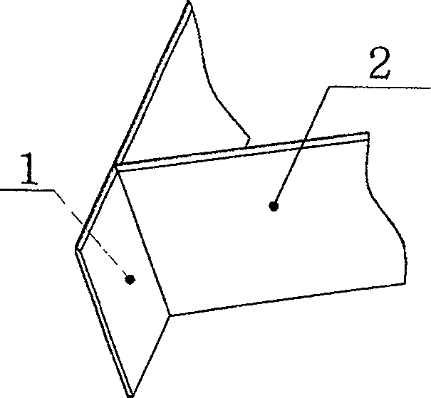
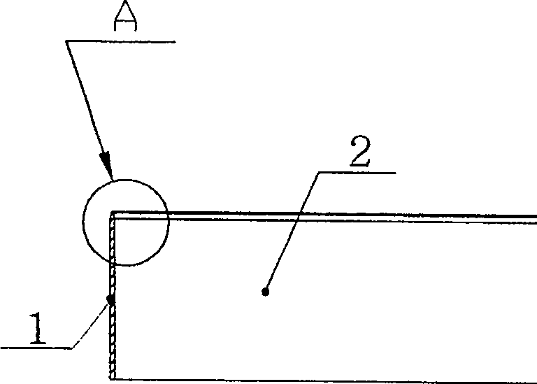
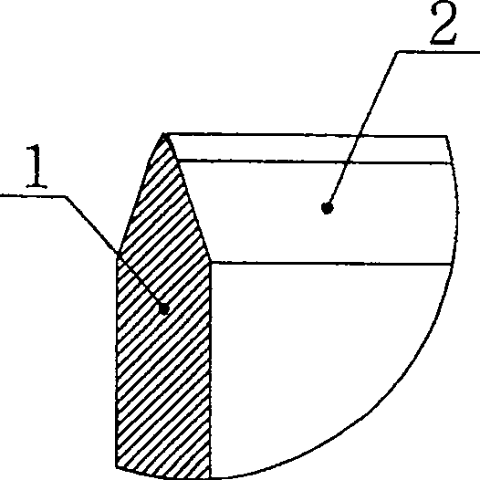
[0032] Such as figure 1 As shown, the connection of the die-cutting blade of the die-cutting die is to install the blade 2 on the side of a straight blade 1 . Such as figure 2 and image 3 As shown, the blade 2 and the blade 1 are in the shape of a cantilever with a gap after being connected. During the die-cutting process, they are subjected to tens of thousands of times of force, and often break and damage, which affects the quality, cost and production cycle of the produced product. . In order to ensure that the material is cut, it is necessary to make the blade 2 coincide with the side of the blade 1 to achieve the best effect. Therefore, the requirements for the connection angle of the blade are higher, and the related equipment and molds are also higher. However, this does not mean easy to do.

[0033] Such as Figure 4 , Figure...


PUM


Abstract

The invention discloses a die-cut knife mold and making method, which is characterized by the following: loading the die-cut blade on the knife mold board; displaying inclined plane among the joint of die-cut blades; coinciding the inclined plane tightly; joining the knife; setting the reinforced part under the joint part; inserting the blade and reinforced part in the knife mold board. The invention supports limits and protects the joint die-cut blade, which improves key part strength, precision, lifetime and product quality of knife mold board.

Description

technical field [0001] The invention relates to a method for making a die-cutting die. Background technique [0002] The die-cutting die is mainly composed of a die-cutting blade and a knife template. It has both the performance of the mold and the cutting tool. It can cut off thin sheet raw materials or press out folding marks, concave-convex effects, etc. It has a wide range of applications and can be used for printed matter and plastic sheets. , insulation boards for electronic products, leather and other thin plates and sheet materials. In the printing and packaging industry, die-cutting is a necessary subsequent process. The method of use is to clamp the die-cutting die in the die-cutting plate frame fixture of the die-cutting machine, and transport the product to the die-cutting platform through the operation of the die-cutting machine , The die-cutting knife die is pressed to die-cut the product. The precision of the die-cutting die determines the quality of the die...

Claims


Application Information

Patent Timeline
Patent Type & Authority Patents(China)
IPC IPC(8): B26F1/44B26D1/00B29D31/00B29D99/00
Inventor 蒋和兴
Owner 汕头和兴隆激光刀模有限公司
Learn More