
Circuit device and method for testing relay switching contacts of a digital output circuit

A circuit device, switch contact technology, applied in relays, circuit breaker testing, circuits, etc., to achieve the effects of energy saving, reliable energy, and cost reduction

Active Publication Date: 2009-02-18
SIEMENS AG
View PDF9 Cites 0 Cited by
  • Summary
  • Abstract
  • Description
  • Claims
  • Application Information

AI Technical Summary

Problems solved by technology

The duration of the brightness test is limited to a maximum of 1 ms, because otherwise the relay connected to the output could be switched on

Method used


Image

  • Circuit device and method for testing relay switching contacts of a digital output circuit
  • Circuit device and method for testing relay switching contacts of a digital output circuit

Examples


Embodiment Construction

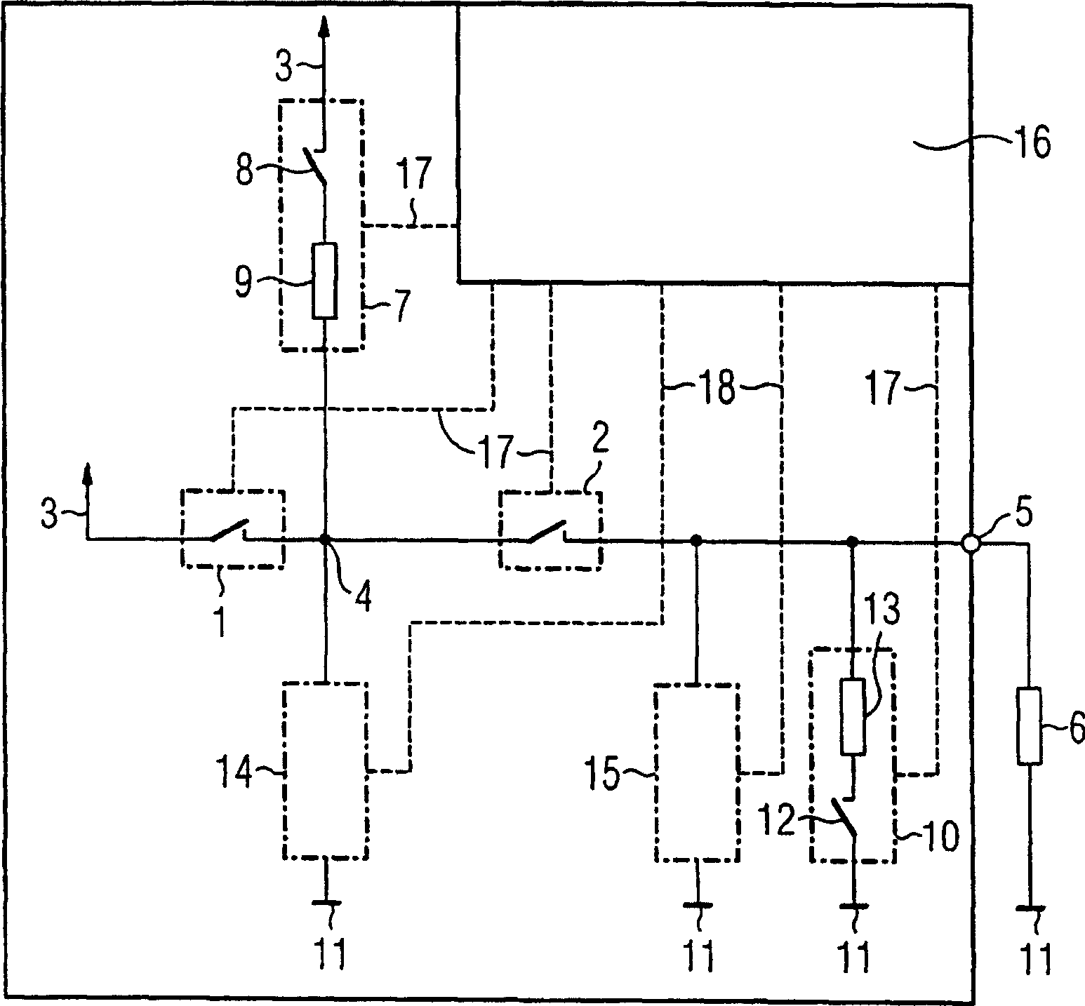
[0019] figure 1 A schematic diagram of a circuit arrangement for a digital output circuit is shown. A series circuit consisting of the first and second switching contacts 1 , 2 of the respective relays, which are not shown in more detail here, is arranged between the supply potential 3 and the output point 5 (eg output terminal) connected to the load 6 . The load 6 is connected between the output point 5 and the reference potential 11 . Connected between the supply potential 3 and the connection point 4 of the first and second switching contacts 1 , 2 is a first circuit 7 comprising a series circuit consisting of a resistive element 9 and a switching element 8 . Connected between the output point 5 and the reference potential 11 is a second circuit 10 comprising a series circuit consisting of a resistive element 13 and a switching element 12 . Furthermore, the circuit arrangement has means 14 , 15 for determining the potentials of the connection point 4 and the output point...


PUM


Abstract

The invention relates to a circuit arrangement for a digital output circuit comprising first and second switching contacts (1, 2) of respective relays. The first switching contact (1) is arranged between the supply potential (3) and the connection point (4) to the second switching contact (2) at which the second switching contact (2) is arranged and the output point (5) connected to the load (6). In order to allow testing of the relay switching contacts (1, 2) without producing a brightness test at the output, the connection point (4) is connected to the supply potential (3) via the first circuit (7). The output point is connected to a reference potential (11) via a second circuit (10). Means (14, 15) are provided for determining the potential of the connection point (4) and the output point (5). Furthermore, the invention also relates to a corresponding method.

Description

technical field [0001] The invention relates to a circuit arrangement for a digital output circuit with first and second switching contacts of respective relays, a control unit for controlling such a circuit arrangement, a circuit arrangement of this type and a control unit of this type A system of units, a digital output circuit having such a circuit arrangement, and a method for checking the first and second switch contacts of the relays of such a circuit arrangement. Background technique [0002] For reasons of reliability technology, digital output circuits in industrial automation technology require fail-safe outputs, which must be checked for switching on and off before they are actually connected. For outputs that only switch one of the potential busbars (for example positive potential), this results in a brief single pulse (so-called Helltest, brightness test) in the event of a load. The duration of the brightness test is limited to a maximum of 1 ms, since otherwis...

Claims


Application Information

Patent Timeline
Patent Type & Authority Patents(China)
IPC IPC(8): G01R31/00G01R31/327G05B9/02G05B9/03H01H47/00
CPCG05B9/02H01H47/002G01R31/3278
Inventor 托马斯·布里姆尔马里奥·梅尔莱因哈德·马克哈特穆特·许茨乔基姆·瓦尔比克勒
Owner SIEMENS AG
Learn More