
Electrical connection device, especially for connecting an outer conductor of a coaxial cable

An electrical connection device, a technology of the connection device, applied in the direction of conductive connection, two-part connection device, and parts of the connection device, etc., can solve the problems of high price, high thermal load and large heat of the shell and cable, and achieve high bending load. Effect

Inactive Publication Date: 2009-02-11
TELEFON AB LM ERICSSON (PUBL)
View PDF11 Cites 0 Cited by
  • Summary
  • Abstract
  • Description
  • Claims
  • Application Information

AI Technical Summary

Problems solved by technology

But doing so leads to a considerable price increase on the one hand
On the other hand, quality problems arise with respect to the homogeneity of the coating thickness when the contour shape is complex
In addition, a large amount of heat is required during brazing, resulting in high thermal loads on the housing and cables
[0013] If the described electrical connection means are located in the electromagnetic plane (e.g. an antenna), some additional hitherto unfamiliar problems arise

Method used


Image

  • Electrical connection device, especially for connecting an outer conductor of a coaxial cable
  • Electrical connection device, especially for connecting an outer conductor of a coaxial cable
  • Electrical connection device, especially for connecting an outer conductor of a coaxial cable

Examples


Embodiment Construction

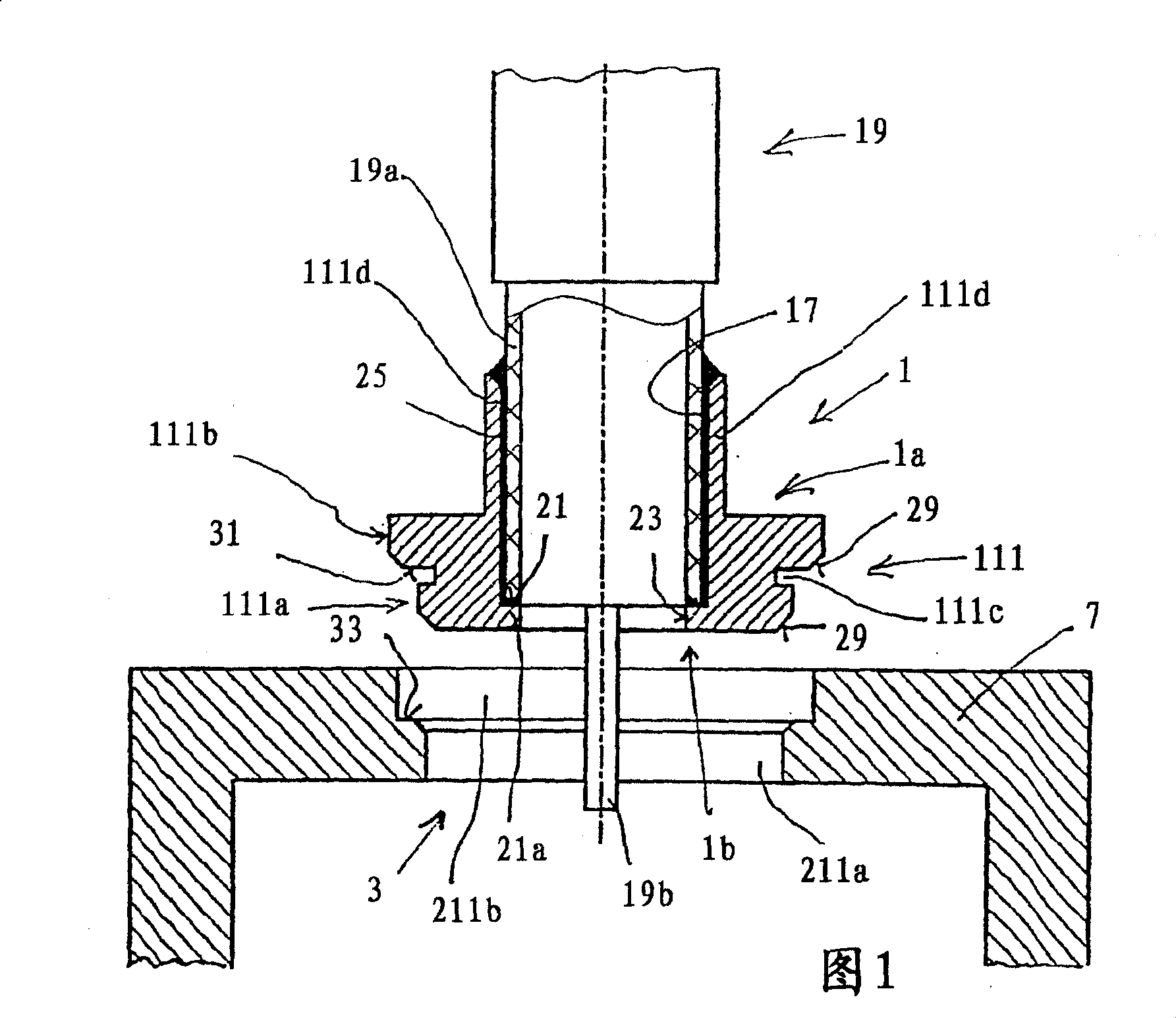
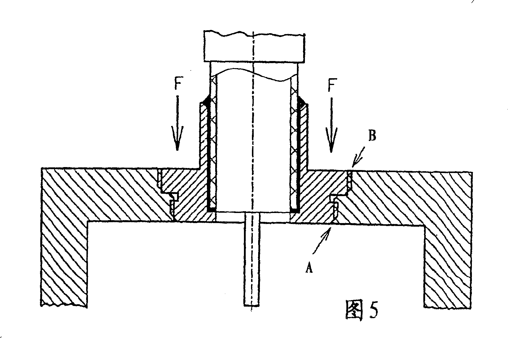
[0062] A first exemplary embodiment will be described in detail below with reference to FIGS. 1 to 5 .

[0063] FIG. 1 schematically shows a cross-section of a coaxial connection device comprising on the one hand a plug-in element 1 and on the other hand an engaging element 3 which, in the illustrated embodiment, is designed in the form of a wall 7 , that is, an electrically conductive housing wall. 7 or in the form of a dual stage hole in the wall 7 forming part of the enclosure.

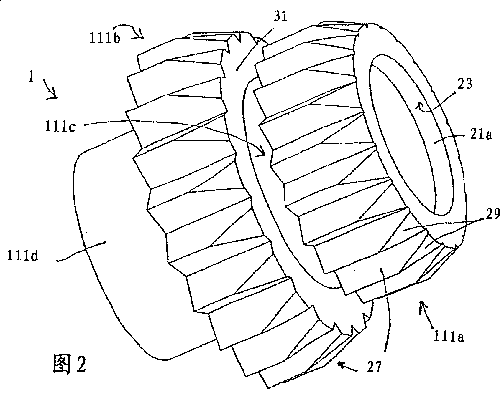
[0064] Here, the plug element 1 is designed in the form of a sleeve and has an actual plug part 111 comprising a leading plug section 111a and a second plug section 111b following in the plugging direction. The two plug-in sections 111a and 111b are arranged offset from each other by a width of the ring groove 111c along the plug-in direction, that is, along the axial direction. The ring groove 111c here has a smaller diameter than the two outer diameters of the plug sections 111a and 111b.

[00...


PUM


Abstract

The termination connection has a plug element (1) with a plug part (111) and a sleeve attachment (111d), for reception of the outer conductor (19a) of the coaxial cable (19), fitting into an opening (3) in a housing wall (7), for providing an electrical connection with the latter. The plug part has 2 axially offset plug sections (111a,111b), the opening having 2 axially offset reception sections (211a,211b) of slightly lesser size.

Description

technical field [0001] The invention relates to an electrical connection device, in particular for connecting the outer conductors of coaxial cables. Background technique [0002] The electrical connection means, in particular for connecting the outer conductors of coaxial cables, usually consists of a plug-in element which can be plugged into a socket or usually into an adapter having a corresponding socket. [0003] Such an engagement device can also be formed, for example, on an electrically conductive metal part, plate, wall, that is to say usually on the housing part or the electrically conductive housing on which, for example, a coaxial cable is to be connected. The inner conductor shall be insulated from the outer conductor and inserted into the inner conductor splice. A coaxial cable provided with a corresponding outer conductor sleeve is brought into contact with the sleeve-like part of the splice device in order to establish an electrical connection of the outer c...

Claims


Application Information

Patent Timeline
IPC IPC(8): H01R13/646H01R9/05H01R13/504
CPCH01R24/52H01R13/5045H01R2103/00H01R9/05
Inventor W·斯坦尼谢夫斯基R·亨奇
Owner TELEFON AB LM ERICSSON (PUBL)
Learn More