Movement mechanism for yarn mouth on intarsia shuttle box

A motion mechanism and yarn feeder technology, applied in textiles and papermaking, weft knitting, knitting and other directions, can solve the problems of inability to increase the running speed of the loom, large transmission gap, vibration and other problems, and achieve the improvement of flat knitting efficiency and transmission gap. Small, the effect of improving the running speed

Inactive Publication Date: 2009-02-11
冯加林
View PDF9 Cites 3 Cited by
  • Summary
  • Abstract
  • Description
  • Claims
  • Application Information

AI Technical Summary

Problems solved by technology

There is inevitably a large transmission gap in this transmission mode, which will produce impact during the switching process, so that vibration and noise will occur during work, so that the running speed of the entire loom cannot be increased. run at gear speed

Method used


Image

  • Movement mechanism for yarn mouth on intarsia shuttle box
  • Movement mechanism for yarn mouth on intarsia shuttle box
  • Movement mechanism for yarn mouth on intarsia shuttle box

Examples


Embodiment Construction

[0021] The present invention will be further described below in conjunction with the accompanying drawings and specific embodiments.

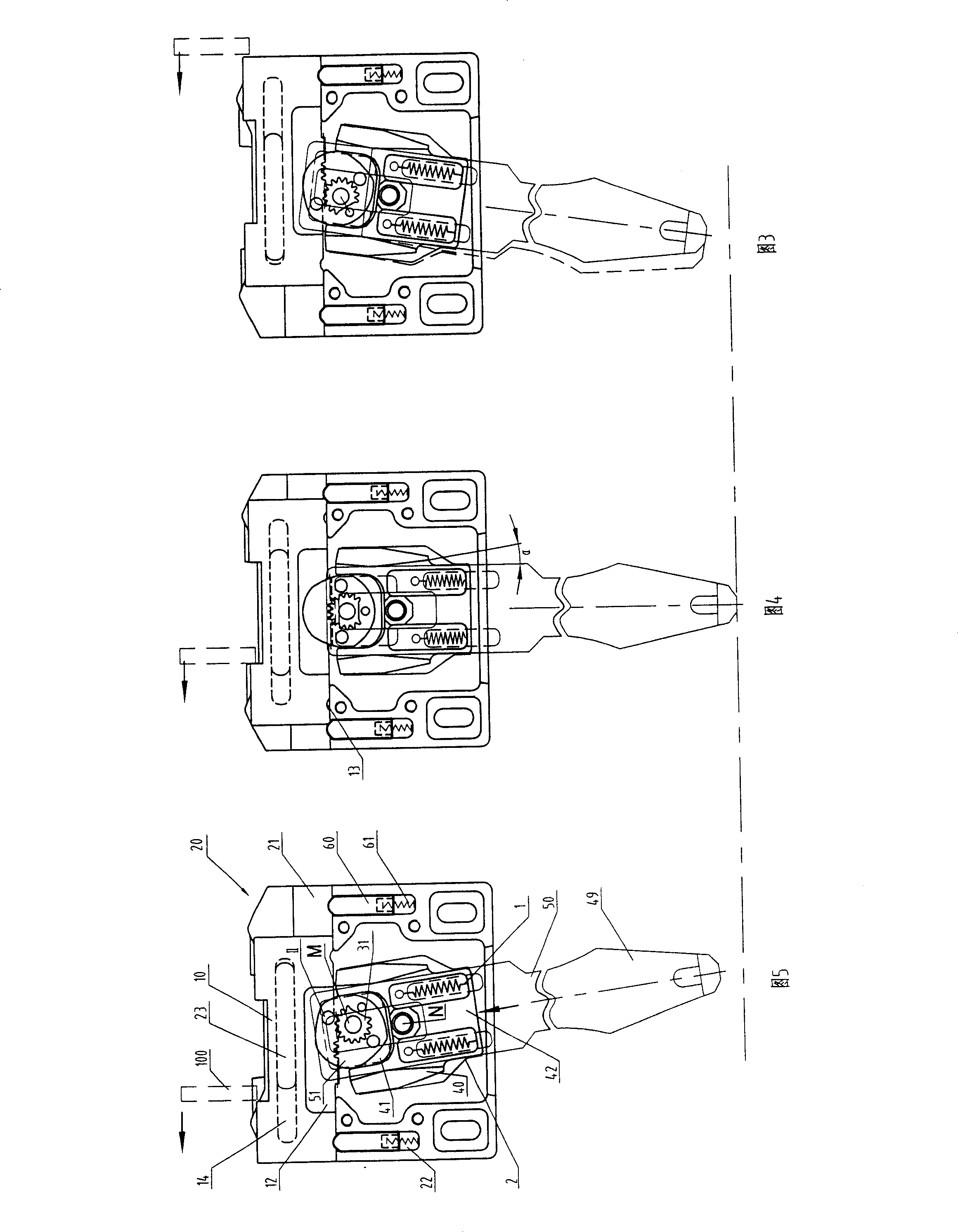
[0022] In the following examples, with figure 1 , figure 2 The projection surface formed by A in the projection direction is outside, and the projection surface formed by B in the projection direction is inside.

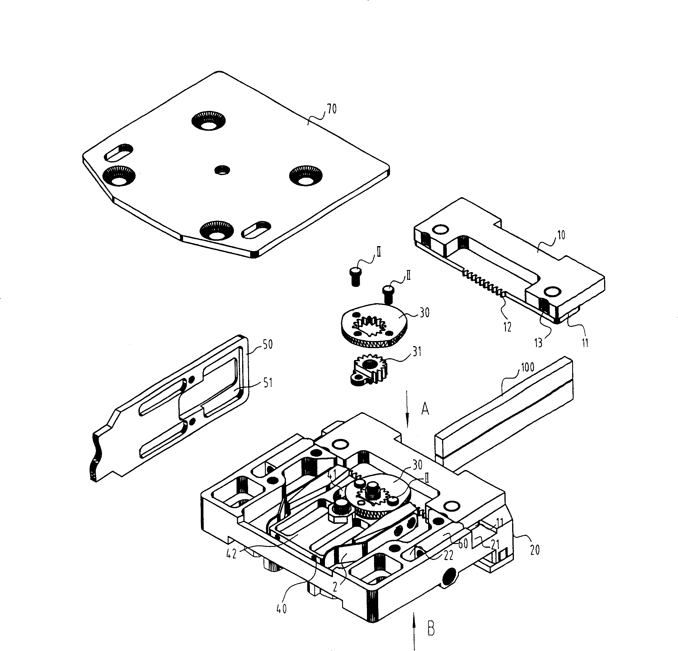
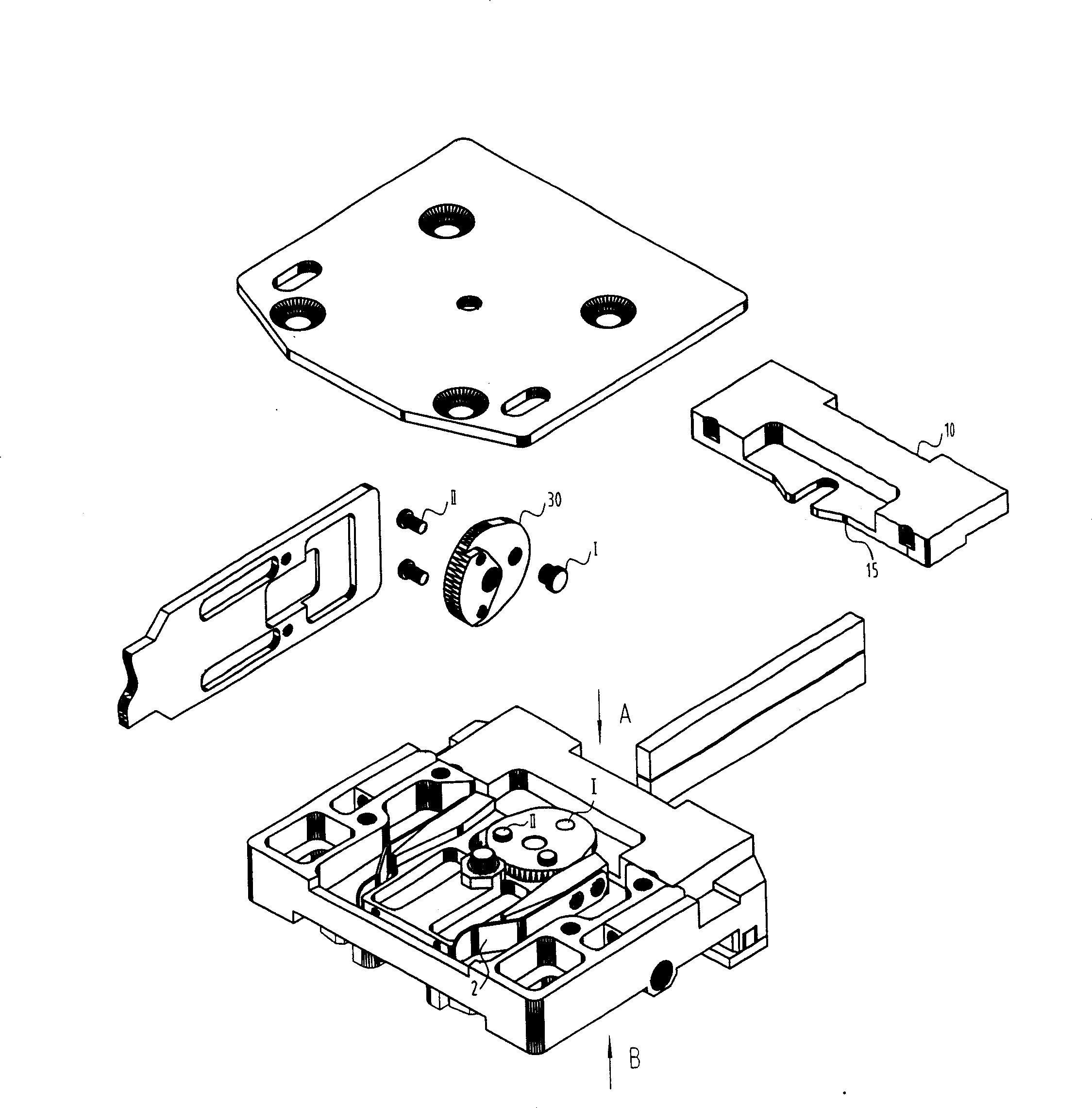
[0023] control figure 1 The sliding connection between the drive plate 10 and the box body 20 is realized by the guide lug 11 provided inside the drive plate 10 and the chute 21 set outside the box body, the guide lug 11 is placed in the chute 21, so that the drive plate 10 slides along the chute 21.

[0024] The sliding of the transmission plate 10 in the chute 21 to both ends must be limited. For this reason, a limiting groove 14 is provided on the inner side of the transmission plate 10 (see FIG. 5 ), and a limiting guide block 23 is provided on the outer side of the box body 20. . The limit guide block 23 is placed in the li...


PUM


Abstract

The inventions relates to a yarn nozzle motion mechanism of intarsia shuttle box in flat knitting machine, comprising case, driving plate, limit swing block, fixed plate for yarn nozzle, outer cover plate and is characterized in that it contains cam, extension spring, buffer spring. Driving plate is slipped on the upper end of case outer and cam, limit swing block are articulated on the case outer under the driving plate from the top down orderly. Fixed plate for yarn nozzle is cut into limit swing block and two ends of extension spring are connected to fixed plate for yarn nozzle and limit swing block respectively. One end of two buffer spring is fixed to two sides of limit swing block and the other end is leaned against two sides of fixed plate for yarn nozzle in press. Driving plate is connected to cam, which is connected to limit swing block and fixed plate for yarn nozzle in driving style. Outer cover plate is connected to the outer of case. The merit is that it makes loom speed and weaving efficiency increase that small driving gap, stable operation, because the rotary of limit swing block is accomplished by pinion-and-rack contacting and cam moving.

Description

technical field [0001] The invention relates to a flat knitting machine, more specifically, a yarn feeder movement mechanism on an intarsia shuttle box in a flat knitting machine. Background technique [0002] In the flat knitting machine, the intarsia shuttle box is a control mechanism that controls the yarn feeder to accurately feed the yarn to the needles at different positions on the needle bed according to the set program. When feeding the thread, the fixed plate connecting the yarn feeder turns downwards, so that the yarn feeder is in the lower position, feeds the thread to the set knitting needle and moves on the shuttle bar with the head of the flat knitting machine. When not feeding the thread, it is locked on a certain position of the shuttle bar. The locking or loosening of the intarsia shuttle box on the shuttle bar is controlled by the locking mechanism on the shuttle box. The yarn feeder turns to the lower position to feed the knitting needles, or turns to the...

Claims


Application Information

Patent Timeline
Patent Type & Authority Patents(China)
IPC IPC(8): D04B15/56
Inventor 冯加林巫友群
Owner 冯加林
Why Eureka
Try Eureka