
Sliding closing element, with coupling

A technology for closing elements and couplings, applied in the direction of connecting components, manufacturing tools, threaded fasteners, etc., can solve problems such as affecting the sliding closing function, control errors, and cumbersome couplings

Inactive Publication Date: 2009-01-07
STOPINC AG
View PDF4 Cites 1 Cited by
  • Summary
  • Abstract
  • Description
  • Claims
  • Application Information

AI Technical Summary

Problems solved by technology

This creates the danger that, due to the pivoting movement and the existing play, control errors will occur during operation, which will therefore affect the sliding closing function
Also, in many cases, the couplings connecting the skateboards to their drive mechanisms are cumbersome

Method used


Image

  • Sliding closing element, with coupling
  • Sliding closing element, with coupling
  • Sliding closing element, with coupling

Examples


Embodiment Construction

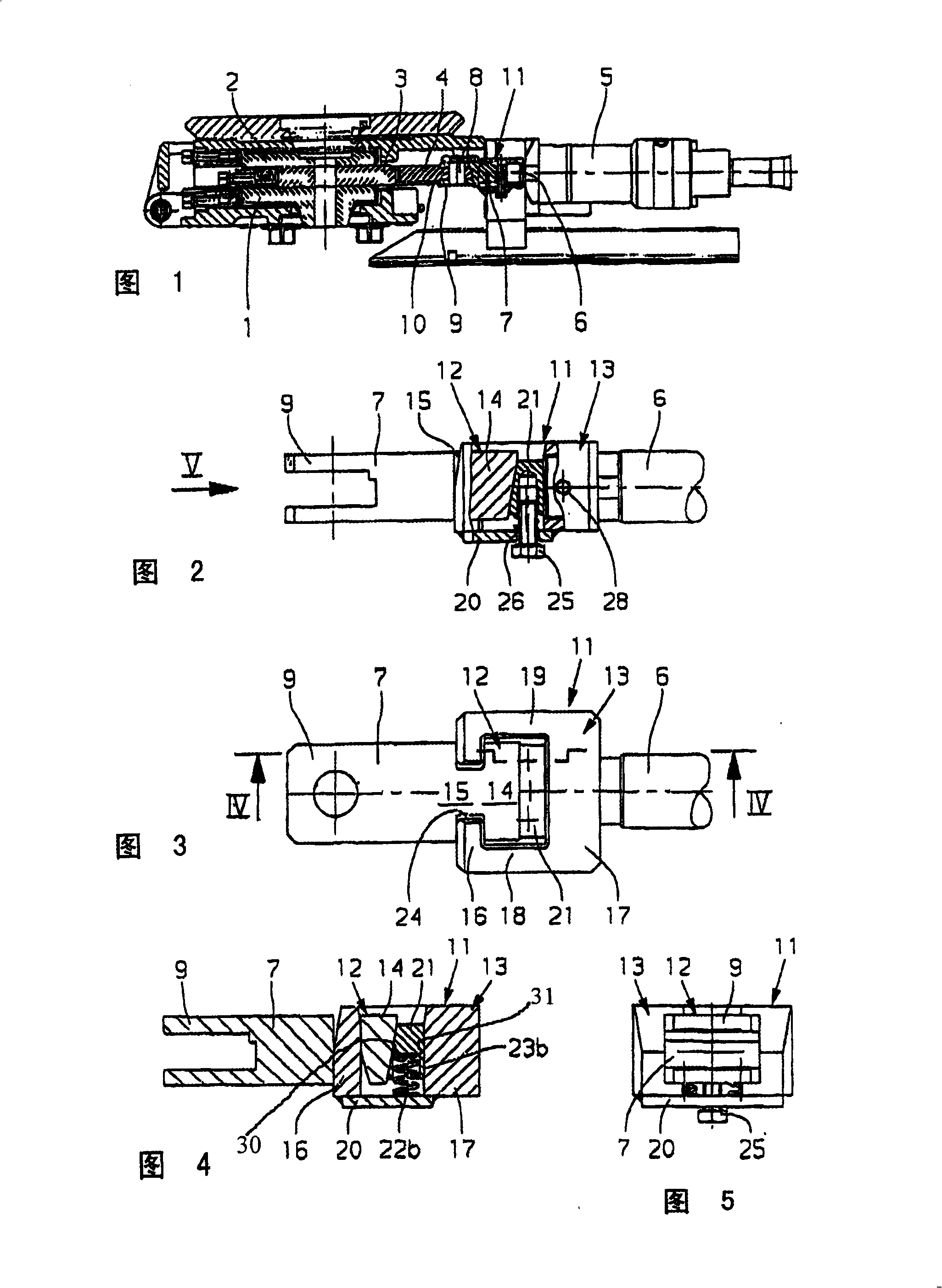
[0029] The sliding closing element shown in Fig. 1 comprises two partially fixed sliding plates 1, 2 on an intermediate distributor (not shown in detail) and a movable sliding plate 3 placed between these two sliding plates, the movable sliding plate being located between the sliding plates Frame 4 is tensioned inside. The slide frame can be driven by a hydraulic cylinder 5, the drive rod 6 of the hydraulic cylinder is connected with a push rod 7, and the push rod 7 is attached to the slide frame 4 together with the movable slide 3. The push rod 7 is fitted with a bolt 8 protruding through the fork-shaped head 9 of the push rod 7 and inserted into the shoulder 10 of the skateboard frame 4 in the fork-shaped head 9 .

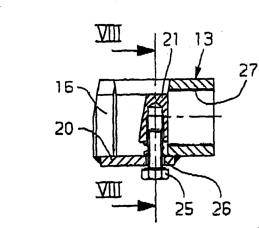
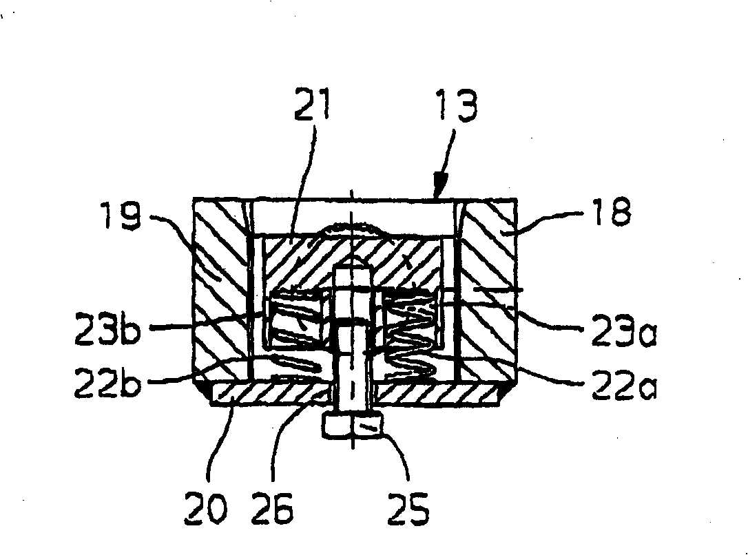
[0030] The coupling between the drive rod 6 and the push rod 7 is produced by means of a coupling 11 which is equipped with a coupling head 12 and a coupling dog 13 which is positively and non-positively received by the coupling head.

[0031] The coupling head ...


PUM


Abstract

The invention relates to a sliding closing element, especially for an intermediate distributor or similar metallurgical containers. According to the invention, the mobile sliding plate of said closing element can be driven by means of a drive comprising a driving road and a push rod connected thereto. In order to ensure that the oscillatory movement of the sliding plate does not impair the connection during operation, a coupling arranged as a connecting body between the opposite ends of the push rod and the driving rod is provided with two coupling parts that engage in each other without play.

Description

technical field [0001] The invention relates to a sliding closing element, in particular for intermediate distributors or similar metallurgical containers, the movable slide of which can be driven by a drive comprising a drive rod and a push rod connected thereto. Background technique [0002] It is known, with regard to such sliding closing elements, that the mobile slide is arranged to oscillate continuously by its drive during operation, and the drive rod and the push rod connected thereto are also subjected to this oscillating motion. [0003] The connection between the push rod and the drive rod has a certain clearance. This creates the risk that, due to the pivoting movement and the existing play, control errors can occur during operation, which would consequently affect the sliding closing function. Additionally, in many cases, the couplings connecting the slides to their drive mechanisms are cumbersome. Contents of the invention [0004] The object of the present...

Claims


Application Information

Patent Timeline
IPC IPC(8): B22D41/38
CPCB22D41/38F16B35/00B22D11/10
Inventor W·克勒
Owner STOPINC AG
Learn More