Infrared touch screen performance improving structure and method

An infrared touch screen and touch screen technology, applied in the field of touch input devices and infrared touch screens, can solve problems such as low touch resolution, failure to solve working life and touch resolution, and touch screen failure.

Inactive Publication Date: 2008-12-10
BEIJING UNITOP NEW TECH CO LTD
View PDF3 Cites 0 Cited by
  • Summary
  • Abstract
  • Description
  • Claims
  • Application Information

AI Technical Summary

Problems solved by technology

[0003] The infrared touch screen composed of the above technical scheme can easily guarantee the performance of a certain pair of infrared transmitting and receiving tubes, but a touch screen needs dozens to hundreds of pairs of tubes. It is also difficult to guarantee the consistent performance of the products, especially when the transmitting tubes work for a period of time, the aging speed is different, resulting in a significant difference, and finally when the photoelectric signal output of a certain receiving tube is too weak, so that the amplifier of the receiving circuit When a large amount is relatively insufficient, it will cause the touch screen to fail, so the working life of the entire touch screen is very short, often only one or two years
At the same time, through the detection principle of judging whether the light of each pair of transmitting and receiving tubes is blocked, its resolution is generally only the same as the logarithm of the transmitting and receiving tubes in each direction. Even if the software is multiplied, the resolution can only be increased by one times
Since the photoelectric components have a certain size, it is impossible to arrange more transmitting and receiving tubes on the edge of the display, so the touch resolution is very low
In addition, the light in the form of pulses is often interfered by electric light sources and natural light, resulting in operational errors and even crashes.
The application number is 95105303 Chinese patent application has announced a method of using pulse counting and width adjustment to make the system work more stable, but the multi-pulse technology will reduce the frequency of scanning, so there is a shortcoming of slowing down the response speed of the system, and at the same time Doesn't address work life and touch resolution issues

Method used


Image

  • Infrared touch screen performance improving structure and method
  • Infrared touch screen performance improving structure and method
  • Infrared touch screen performance improving structure and method

Examples


Embodiment Construction

[0096] Embodiments of the present invention for realizing the purpose of the present invention and corresponding detection methods will be described below according to the above drawings. For software and hardware engineers, words such as "device" used to describe the software structure or process are not easy to understand. Therefore, in the embodiments, words such as codes that are more common in the industry are used instead of descriptions.

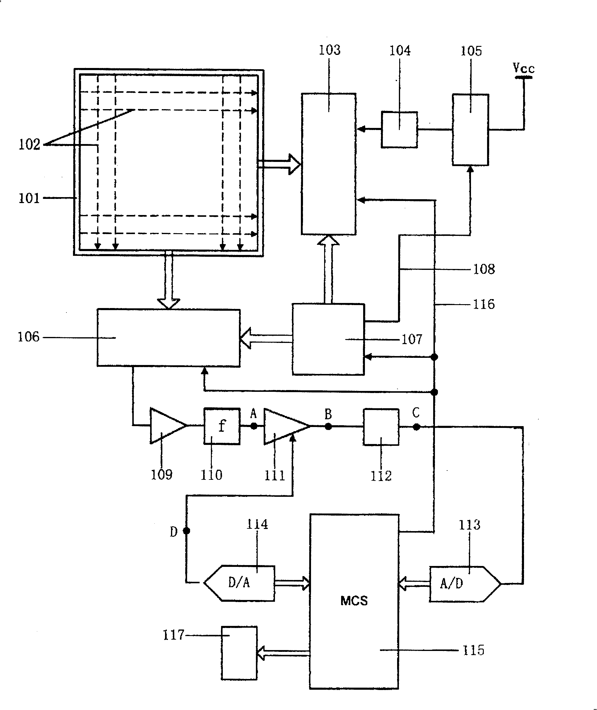
[0097] figure 1 A general physical structure diagram of the present invention is given. From figure 1 It can be seen that the array of infrared transmitting and receiving tubes is installed on the frame 101 that constitutes the working area, and is divided into vertical and horizontal directions to form a transmitting-receiving array; where two transmitting tubes and receiving tubes form a pair, and are installed on the frame relative to each other. Inside 101; the infrared rays emitted by the emitting tube are shown as 102 in the f...


PUM


Abstract

The present invention is mainly inserting one A / D converting link in the photoelectronic signal channel to realize the predetection of the monochip computer system to the photoelectronic element performance and the data normalization in touch judging process, with the data being provided to curve-fitting touth point calculating module. At the same time, one digital controlled gain link is inserted into the same channel to constitute with the monochip computer system one gain controlling loop. Based on the predetection result, the gain is regulated and normalized and this can make up the performance difference of elements and prolong the service life.

Description

technical field [0001] The invention relates to a touch input device applied on the surface of a display screen, in particular to an infrared touch screen using infrared rays as a sensing medium, and belongs to the technical field of computer multimedia. Background technique [0002] As the simplest and mature computer multimedia human-computer interaction device, the touch screen has been widely used. Existing touch screen technologies mainly include several forms such as resistive film, capacitor, surface acoustic wave and infrared. Among these touch screen technologies, the infrared touch screen has been greatly developed due to its advantages of simple production process and low production cost, and has been applied in many fields. The basic structure of the infrared touch screen is to install many pairs of infrared emitting and receiving tubes in a certain order along the four edges of the display surface in a frame suitable for installation on the edge of the display;...

Claims


Application Information

Patent Timeline
IPC IPC(8): G06F3/02
Inventor 刘建军刘新斌
Owner BEIJING UNITOP NEW TECH CO LTD
Why Eureka
Try Eureka