
Coil system for an mr apparatus and an mr apparatus provided with such a coil system

A magnetic resonance and coil technology, which is applied in the direction of measuring devices, measuring magnetic variables, medical science, etc., can solve the problems of reducing the free inner diameter and complexity of the coil system, and achieve the effect of reducing volume

Inactive Publication Date: 2008-11-26
KONINKLIJKE PHILIPS ELECTRONICS NV
View PDF6 Cites 0 Cited by
  • Summary
  • Abstract
  • Description
  • Claims
  • Application Information

AI Technical Summary

Problems solved by technology

[0009] Furthermore, in order to reduce the energy required by the gradient and radio frequency coils, the document EP-A1-0307981 proposes the use of a combined radio frequency and gradient coil system which enables a reduction of the free inner diameter of the coil system
[0010] In both cases, the coil system adapted to achieve the reduced energy consumption of gradient coils is relatively sophisticated and complex

Method used


Image

  • Coil system for an mr apparatus and an mr apparatus provided with such a coil system
  • Coil system for an mr apparatus and an mr apparatus provided with such a coil system

Examples


Embodiment Construction

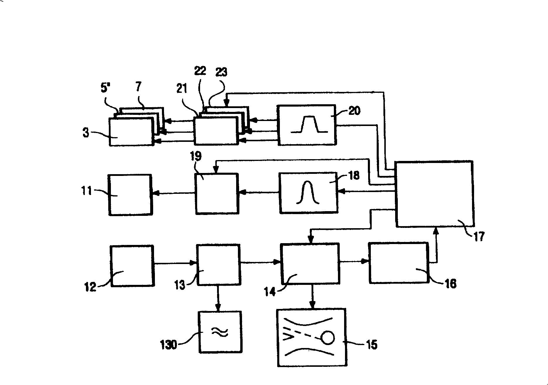
[0021] figure 1 A circuit diagram of a magnetic resonance apparatus suitable for using the coil system according to the invention is shown. It comprises a control unit 17 controlling a gradient waveform generator 20; first, second and third gradient amplifiers 21, 22, 23 are connected to the output of the generator 20, respectively. Each of these amplifiers generates a corresponding current for the first, second and third gradient coils 3, 5, 7 respectively. The gain factors of these amplifiers can be adjusted independently of each other by the control unit 17, that is, via the wires, so that the gradient coils 3, 5, 7 generate gradient fields in the x, y and z directions and correspond to three in the area to be examined. Slice selection can be performed in the spatial direction.

[0022] Furthermore, the control unit 17 controls the radio frequency generator 18 in order to adjust the frequency of the radio frequency pulses to the Larmor frequency, which for magnetic resona...


PUM


Abstract

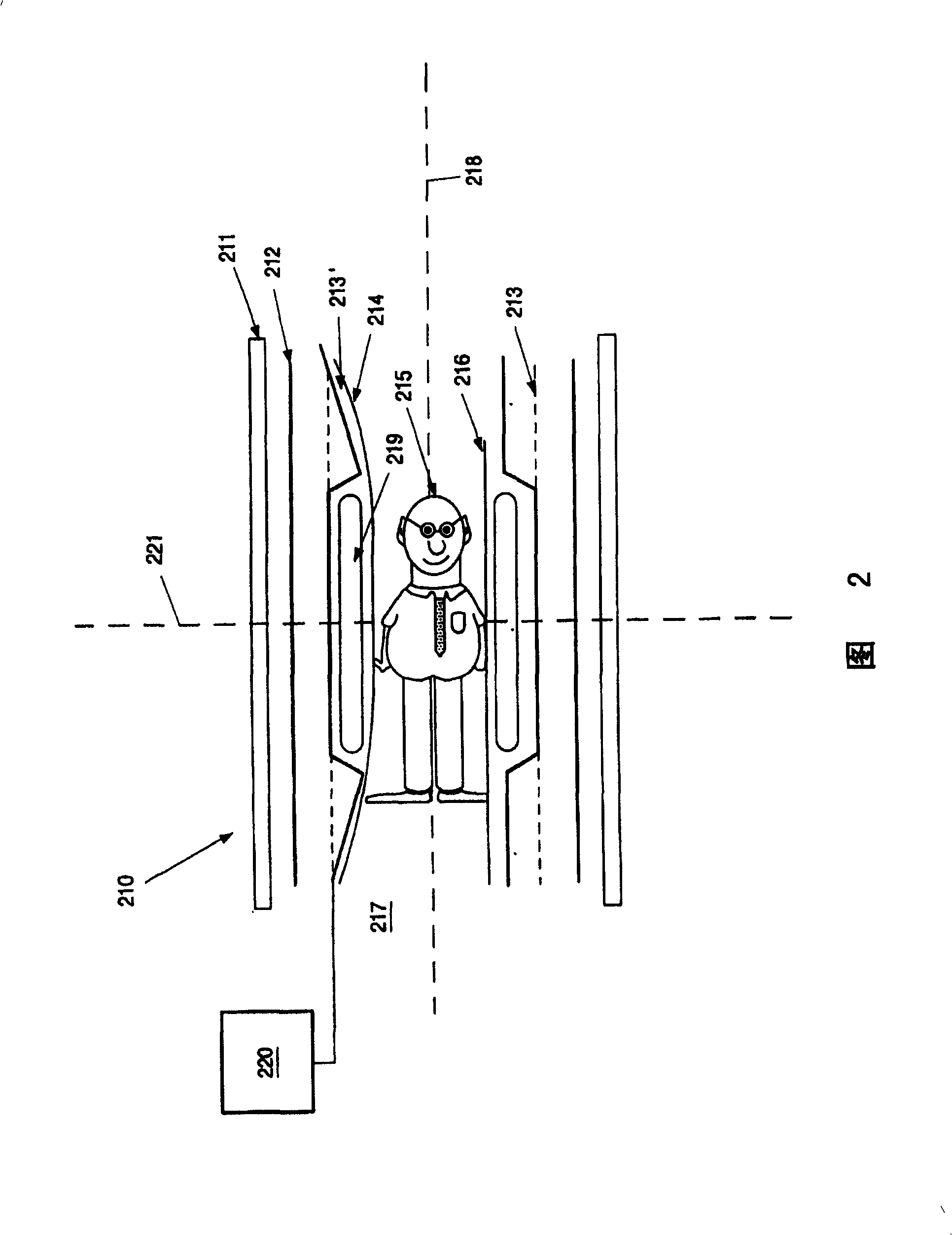
A coil system (210) for an apparatus operating in conformity with the spin resonance or magnetic resonance (MR) method encloses an examination space (217) which extends along an axis (218) and is intended to receive a patient (215). It includes an inner RF coil (219), an inner sub-coil (213') which externally encloses the RF coil (219) and projects beyond the RF coil (219) in the axial direction at both sides, and an active shield (212) which externally encloses the inner sub-coil (213') and constitutes a gradient coil arrangement in conjunction with the inner sub-coil (213'). For specified gradients, the energy required for the gradient coil arrangement (213', 212) in such a coil system is reduced in that the volume occupied by the inner sub-coil 213' is extended in the axial direction by way of regions extending beyond the RF coil (219) in the direction of the axis (218). It is an essential aspect that generally three gradient coils are accommodated in the volume enclosed by the gradient coil arrangement (213', 212). This layered arrangement produces three mutually perpendicular gradient fields as usual. However, it is not necessary to calculate these fields to be such that they extend perpendicularly to one another. All three coil arrangements per se require a smaller energy component in comparison with the normal case.

Description

technical field [0001] The invention relates to the field of magnetic resonance tomography. More specifically, it relates to coil systems. It also relates to a magnetic resonance apparatus comprising a coil system of this type. [0002] A coil system of the proposed type is known, for example, from EP-A1-0304126. Background technique [0003] Magnetic resonance imaging (MRI), which utilizes the interaction between magnetic fields and atomic nucleus spins to form two-dimensional or three-dimensional images, is being remarkably used for numerous applications in the field of medical diagnosis, because in many Imaging them is superior to other imaging methods in that they do not require ionizing radiation and are generally not invasive. [0004] According to the magnetic resonance method, the body to be examined is introduced into a strong and homogeneous magnetic field whose direction at the same time defines the axis (usually the z-axis) of the coordinate system on which th...

Claims


Application Information

Patent Timeline
Patent Type & Authority Patents(China)
IPC IPC(8): G01R33/385A61B5/055
CPCG01R33/385
Inventor V·舒尔兹B·格莱奇J·维泽内克
Owner KONINKLIJKE PHILIPS ELECTRONICS NV
Learn More