Drive apparatus for frame deflection and method

A device and driver technology, applied in the field of deflection compensation, which can solve problems such as adverse effects on image quality

Inactive Publication Date: 2008-11-05
ENTROPIC COMM INC
View PDF7 Cites 0 Cited by
  • Summary
  • Abstract
  • Description
  • Claims
  • Application Information

AI Technical Summary

Problems solved by technology

[0005] However, the magnetic fields generated by complementary coils may have an adverse effect on image quality
In addition, this embodiment has the problem of requiring special complementary coils

Method used


Image

  • Drive apparatus for frame deflection and method
  • Drive apparatus for frame deflection and method
  • Drive apparatus for frame deflection and method

Examples


Embodiment Construction

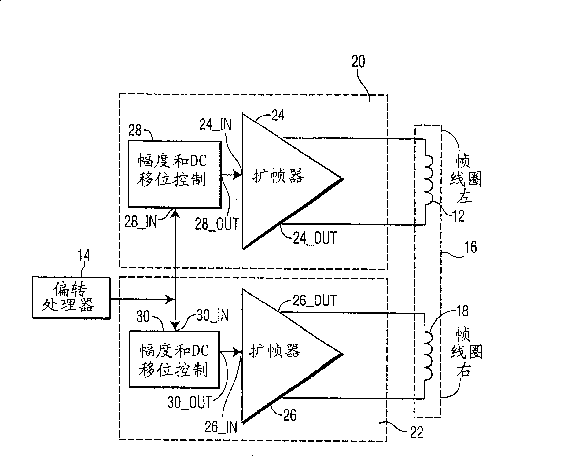
[0016] now, see figure 1 , shows a frame drive circuit for a CRT device such as a CRT monitor or a CRT television, and the drive circuit includes a deflection processor 14 and a frame coil 16 . According to the invention, the frame drive circuit includes a first 12 and second 18 half core or coil half of the frame coil 16 and a first coil driver 20 and a second coil driver 22 .

[0017] The deflection processor 14 generates a deflection processor output signal, as is known. The deflection processor output signal is provided to each of the first driver 20 and the second driver 22 . The first driver 20 and the second driver 22 are each selected to operate independently of the other to generate a first coil drive signal and a second coil drive signal, respectively, as a function of the deflection processor output signal. The first coil drive signal and the second coil drive signal are in turn provided to a respective one of the first core or coil half 12 and the second core or ...


PUM


Abstract

The present invention provides a frame drive circuit for a CRT device having a deflection processor (14) which develops a deflection processor output signal includes a frame coil (16) having a first core half (12) and a second core half (18), and a first driver (20) and a second driver (22). The deflection processor output signal is applied to each of the first driver (20) and the second driver (22). Each of the first driver (20) and the second driver (22) are selectively operative independently of each other to develop respectively a first coil drive signal (24 OUT) and a second coil drive signal (26 OUT) as a function of the deflection processor output signal. The first coil drive signal (24 OUT) and the second coil drive signal (26 OUT) are applied to a respective one of the first coil half (12) and said second coil half (18).

Description

technical field [0001] The present invention relates to deflection compensation in cathode ray tube (CRT) devices such as monitors or television sets, and in particular to devices and methods for correcting various forms of deflection including rotational, trapezoidal and parallelogram deflection. Background technique [0002] CRT devices form images using electron beams focused on a fluorescent screen by electromagnetic deflection. Deflection is achieved by applying a sawtooth-shaped current to the horizontal and vertical coils. [0003] A typical monitor is used as a peripheral to a computer, providing video signals and the horizontal and vertical synchronization signals needed to form an image on the monitor. The electron gun forms electron beams according to the video signal. The electron beams are deflected horizontally and vertically according to the horizontal and vertical synchronous signals by using the horizontal and vertical coils on the front of the phosphor sc...

Claims


Application Information

Patent Timeline
Patent Type & Authority Patents(China)
IPC IPC(8): H04N3/233H04N3/223
CPCH04N3/233H04N3/223H04N3/16
Inventor A·P·D·德波
Owner ENTROPIC COMM INC
Why Eureka
Try Eureka