
A veneered raised panel element and method of manufacturing thereof

A veneer and component technology, applied in the field of veneer convex plate components and their manufacturing, can solve problems such as instability, warpage, lack of aesthetics, etc., and achieve the effects of strength improvement, warpage reduction, and appearance coordination

Inactive Publication Date: 2008-09-24
HOLLMAN
View PDF12 Cites 0 Cited by
  • Summary
  • Abstract
  • Description
  • Claims
  • Application Information

AI Technical Summary

Problems solved by technology

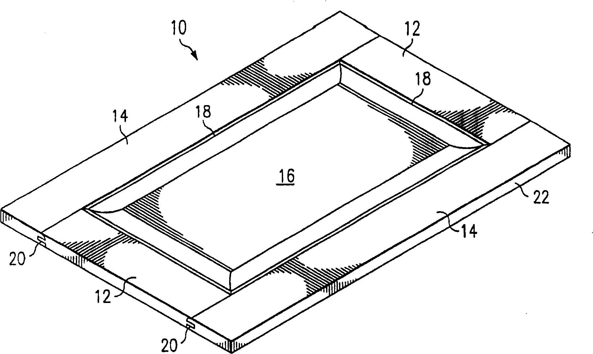
In addition, the ends of the stiles 14 adjacent to the ribs of the rail 12 would expose the transverse grain of the wood, which would not match the wood on the sides of the adjacent rail and would not be aesthetically pleasing
Also, the end grain absorbs moisture faster than the side grain, creating the danger of warping and instability

Method used


Image

  • A veneered raised panel element and method of manufacturing thereof
  • A veneered raised panel element and method of manufacturing thereof
  • A veneered raised panel element and method of manufacturing thereof

Examples


Embodiment Construction

[0028] The making and using of the presently preferred embodiments are discussed in detail below. It should be appreciated, however, that the present invention provides many applicable inventive concepts that can be embodied in a variety of forms as described. The specific embodiments discussed are merely illustrative of the making and using of the invention, and do not limit the scope of the invention.

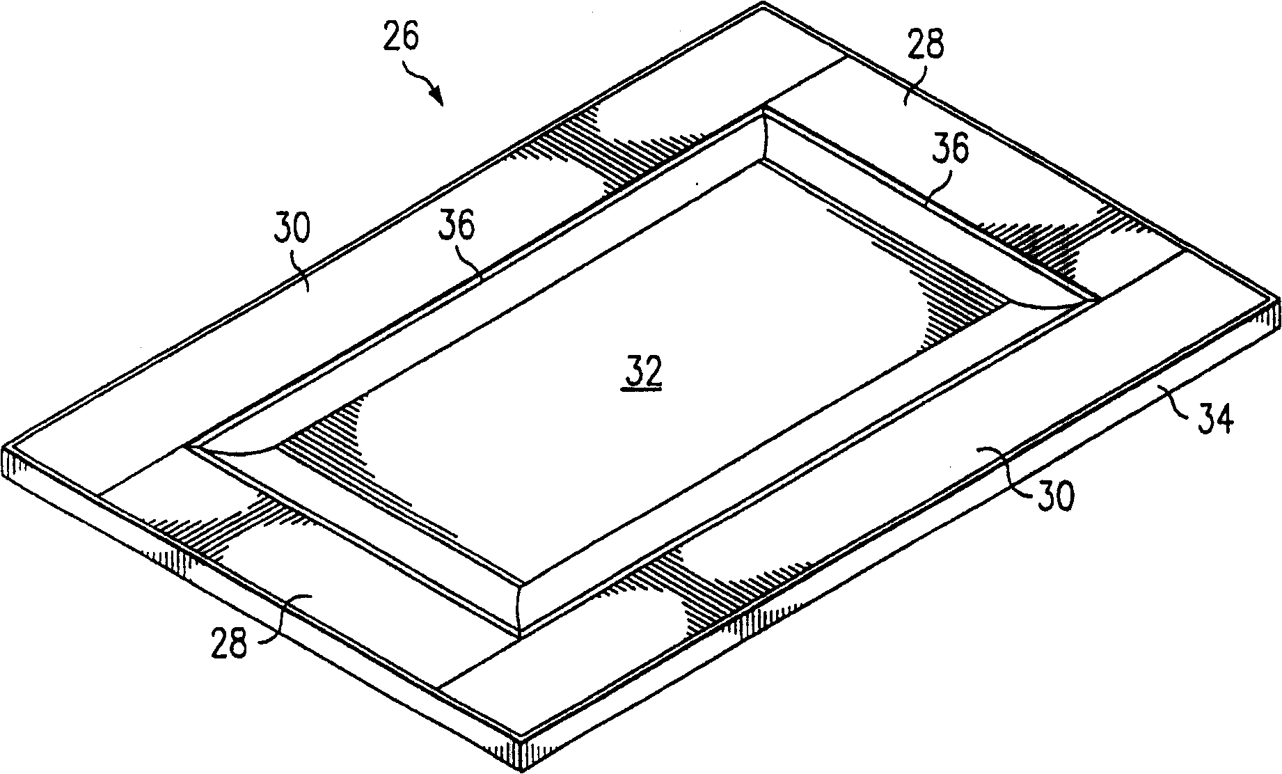
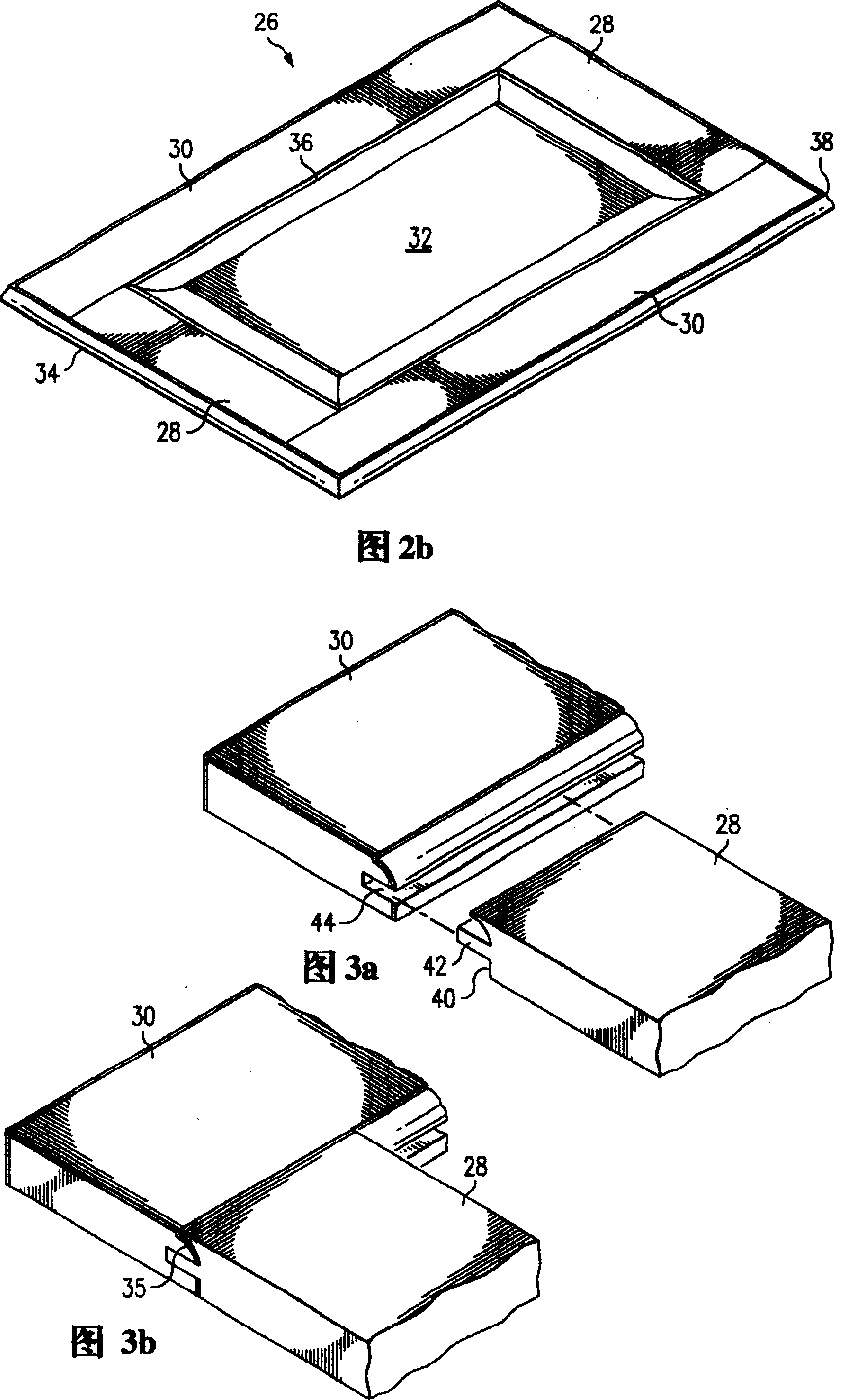
[0029] refer to Figure 2a and 2b, an isometric view of a preferred embodiment of a raised panel door 26 is shown. The door 26 includes horizontally oriented elements or rails 28 , vertically oriented elements or stiles 30 , a central panel 32 and side bars 34 . Overlay veneer veneers over a fabrication material such as pressed wood, medium density fiberboard (MDF), particle board, chipboard or other engineered core material to form rails 28, stiles 30 and center panels 32 . Both rail 28 and stiles 30 include inner edges 36 which may be of simple construction or profiled ...


PUM


Abstract

The present invention relates to veneered paneled elements such as doors. For example, a veneered raised panel door could include two vertically-oriented framing members (e.g., stiles) and two horizontally-oriented framing members (e.g., rails). These members are combined with a center panel to create a door frame. Each exposed edge of the door is layered with an edge banding. This edge banding (e.g., a wood or plastic veneer) covers any joints between the vertically-oriented and horizontally oriented framing members.

Description

technical field [0001] The present invention relates generally to methods of making elements such as doors, and more particularly to veneered raised panel elements such as doors and methods of making the same. Background technique [0002] Raised panel doors have been a part of the building and closet industry for many years. Such as figure 1 As shown, the raised panel door 10 generally includes five components: two rails 12 , two stiles 14 , and a central panel 16 . When the rails 12 and stiles 14 are assembled, the resulting final structure is the outer frame 22 of the door 10 . The rails 12 form the horizontal part of the door 10 and the stiles 14 form the vertical part of the door 10 . [0003] During the manufacturing process, the rail 12 and the door stile 14 are machined using a machine such as a soft forming machine (not shown), which processes grooves on the inner edge 18 of the door stile 14 and the rail 12, while both ends The tenon machine forms a cope at the...

Claims


Application Information

Patent Timeline
Patent Type & Authority Patents(China)
IPC IPC(8): B27M3/00B27M3/18B27D5/00E06B3/70B29C63/00A47B96/20E06B3/74
CPCB27D5/006E06B3/74B29C63/0039B27D5/003B27M3/18B27M3/0093
Inventor 乔·霍尔曼
Owner HOLLMAN
Learn More