
Motorcycle braking device

A motor two-wheeled vehicle and braking device technology, applied in the direction of brakes, etc., can solve problems such as load reduction and poor braking feeling, and achieve the effect of ensuring braking feeling, proper braking feeling, and good braking feeling

Inactive Publication Date: 2008-08-27
HONDA MOTOR CO LTD
View PDF7 Cites 0 Cited by
  • Summary
  • Abstract
  • Description
  • Claims
  • Application Information

AI Technical Summary

Problems solved by technology

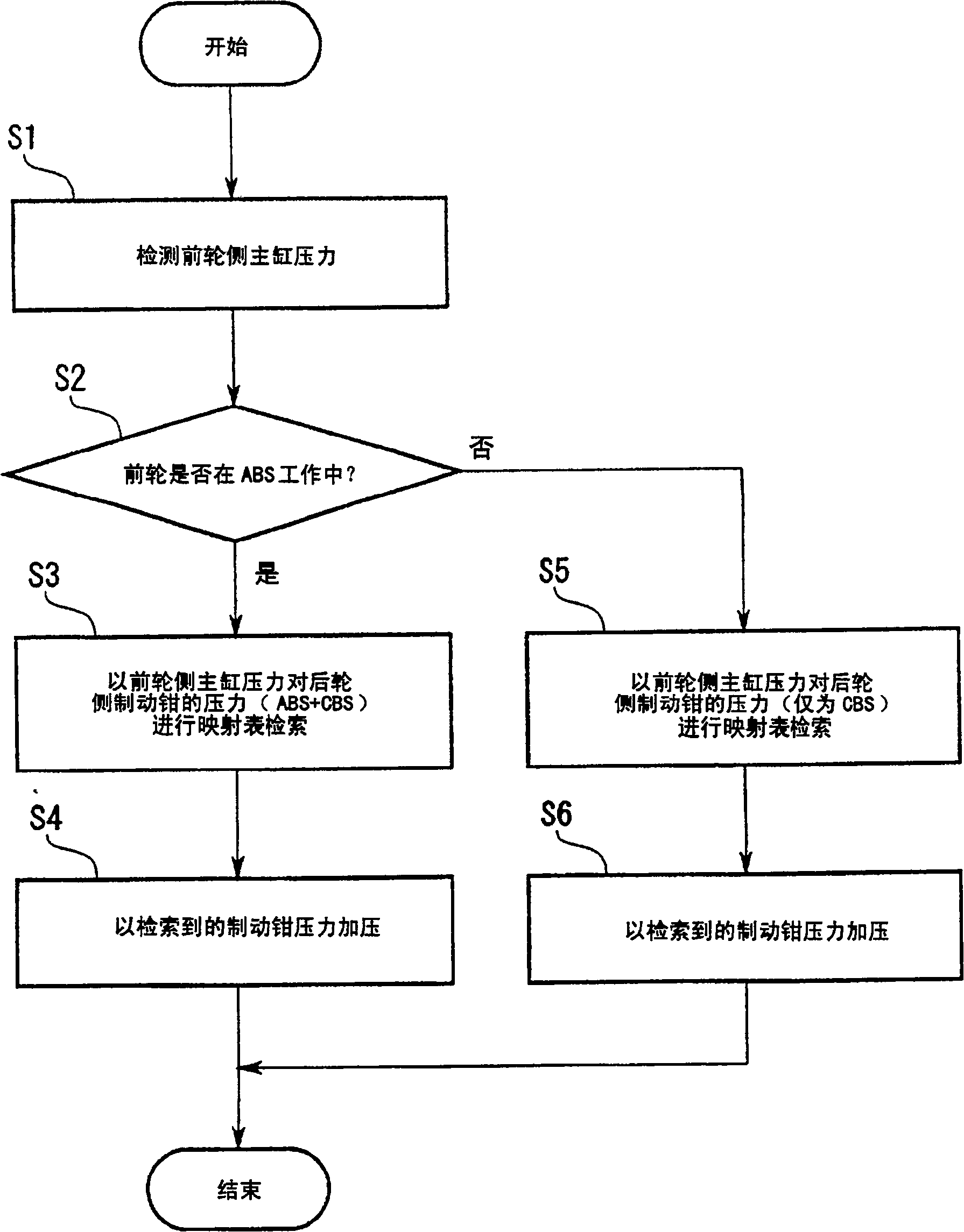
[0004] However, in the above-mentioned conventional braking device for motorcycles, the front and rear brake pressures are completely determined by the characteristics of the oil pressure regulating valve. When the brake system (ABS: ANTI LOCK BRAKE SYSTEM, hereinafter referred to as "ABS") is controlled by coefficient, when the front wheel brake is operated, once the ABS on the front wheel side is activated, the rear wheel side is compared with the front wheel side, and the tire Loads in contact with the ground will produce a large reduction and make the brakes feel bad

Method used


Image

  • Motorcycle braking device
  • Motorcycle braking device
  • Motorcycle braking device

Examples


Embodiment Construction

[0026] Embodiments of the present invention will be described below with reference to the drawings.

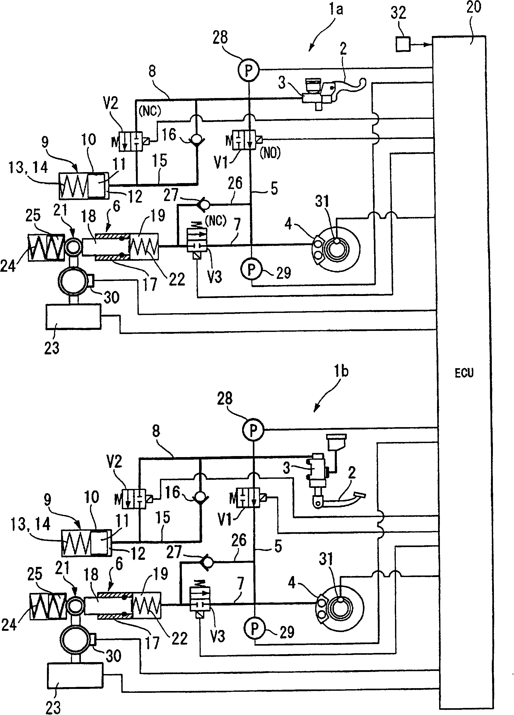
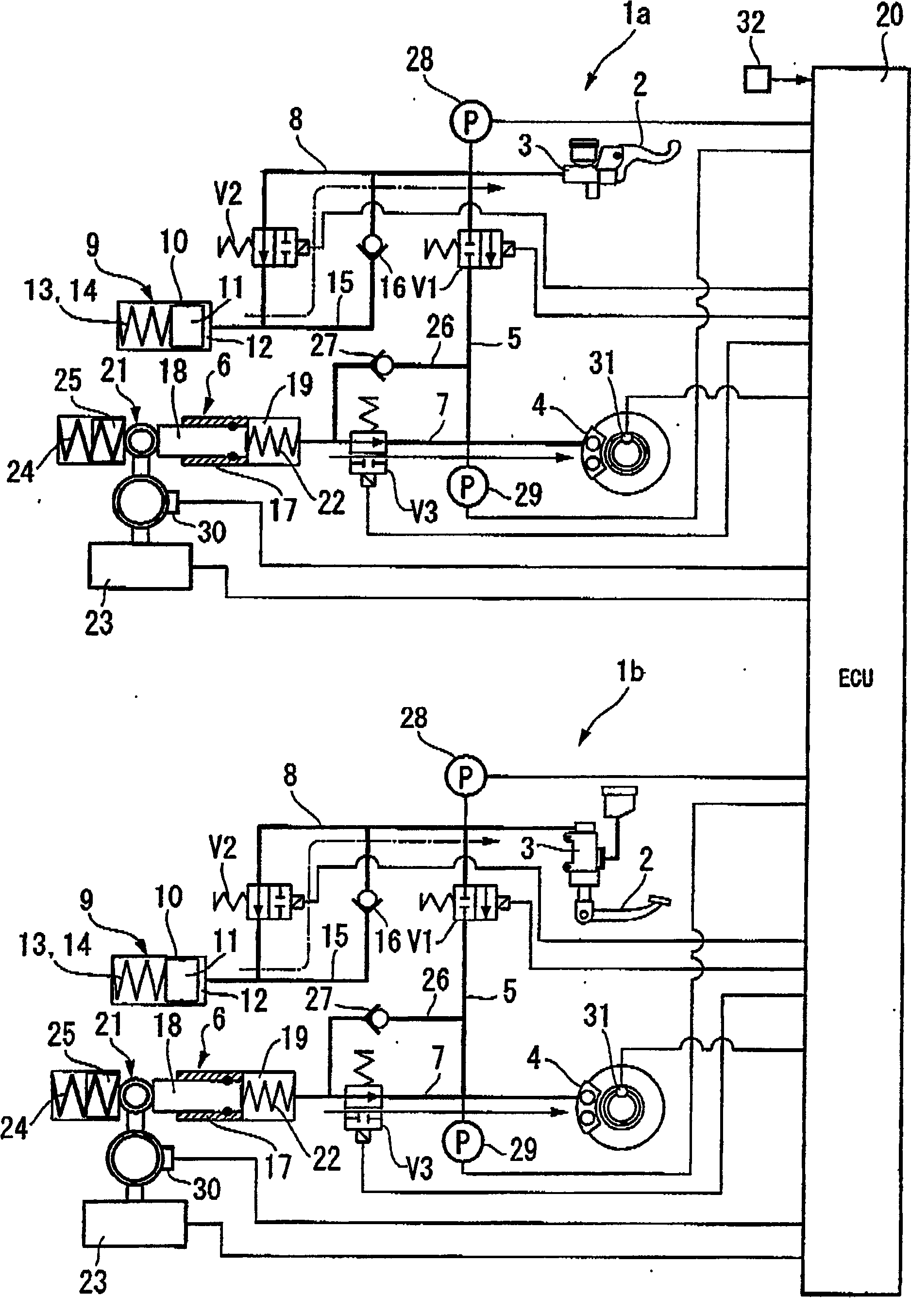
[0027] figure 1 It is a hydraulic circuit diagram showing a motorcycle braking device according to an embodiment of the present invention. As shown in the figure, the braking device of this embodiment has a structure in which mutually independent front wheel side brake circuits 1 a and rear wheel side brake circuits 1 b are connected through a controller (ECU) 20 .

[0028] The brake operation is performed by the brake lever as the brake operation part 2 in the brake circuit 1a on the front wheel side, and by the brake lever as the brake operation part 2 in the brake circuit 1b on the rear wheel side. pedal, but other than that, the brake circuit 1a on the front wheel side is basically the same as the brake circuit 1b on the rear wheel side, so only the brake circuit 1a on the front wheel side will be described in detail. The parts of the brake circuit 1b on the front wheel ...


PUM


Abstract

The invention provides a braking system which improves the brake feeling on a motorcycle and which uses a front-rear interlocking brake system. In a motorcycle braking device in which a brake caliper for a rear wheel works in conjunction with brake operation for a front wheel and the ABS is equipped, when the ABS is active on the side of the front wheel which is braked by a front wheel brake controller, the braking pressure ratio between the brake caliper for the front wheel and the brake caliper for the rear wheel is different from that when the ABS is inactive.

Description

technical field [0001] The invention relates to a brake device for a motorcycle. Background technique [0002] A brake device for a motorcycle includes a device for interlocking a brake operation on a rear wheel side with a wheel brake device on a front wheel side. For example, if the brake lever on the front wheel side is operated, while the brake pressure acts on the brake calipers on the front wheel side through the master cylinder, part of the pressure acting on the master cylinder also acts on the rear through the oil pressure regulating valve. The calipers on the wheel side brake the rear wheel side. (Refer to Patent Document 1). [0003] [Patent Document 1] Japanese Patent Laid-Open No. 04-368267 [0004] However, in the above-mentioned conventional braking device for motorcycles, the front and rear brake pressures are completely determined by the characteristics of the oil pressure regulating valve. When the brake system (ABS: ANTI LOCK BRAKE SYSTEM, hereinafter ...

Claims


Application Information

Patent Timeline
Patent Type & Authority Patents(China)
IPC IPC(8): B60T8/1766
CPCB60T8/3225B60T8/261B60T8/26B60T8/34
Inventor 中山昌宣竹之内和也谷一彦
Owner HONDA MOTOR CO LTD
Learn More