
Coupling for a steel spiral flexible hose

A technology of spiral hose and connector, applied in the direction of hose connection device, pipe/pipe joint/pipe fitting, application, etc., to achieve the effect of reliable fixation

Inactive Publication Date: 2008-08-20
卡尔・温霍尔德
View PDF3 Cites 0 Cited by
  • Summary
  • Abstract
  • Description
  • Claims
  • Application Information

AI Technical Summary

Problems solved by technology

The disadvantage of this known connector is that the clamping clip is only suitable for a perfectly defined hose with a perfectly defined steel helical pitch

Method used


Image

  • Coupling for a steel spiral flexible hose
  • Coupling for a steel spiral flexible hose
  • Coupling for a steel spiral flexible hose

Examples


Embodiment Construction

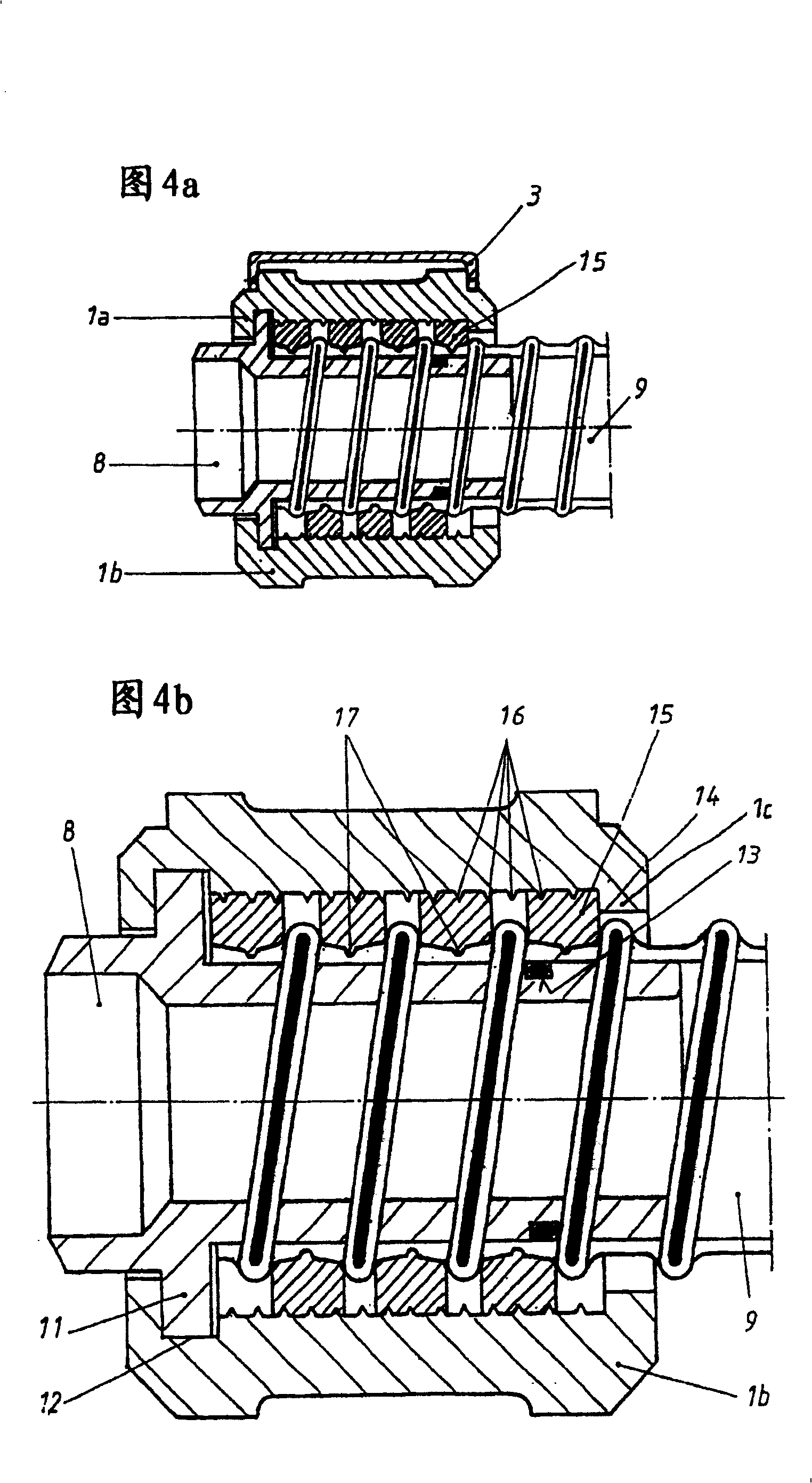
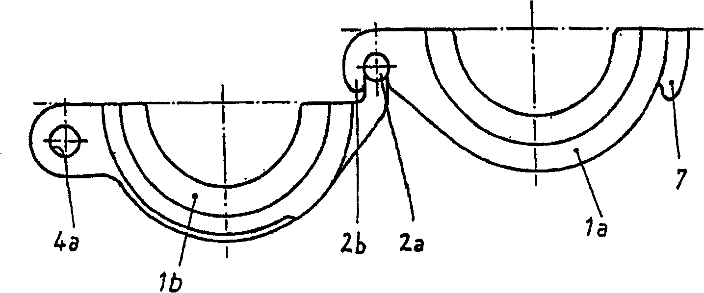
[0020] Figures 1 to 3 show three different views of the connector of the invention. The core part of the connector is a clamping clip 1 which, in the illustrated and therefore preferred embodiment, comprises two separate partial shells 1a and 1b. As can be seen in particular from FIGS. 1 and 3, the two partial shells are hingedly connected to each other via a hinge 2, wherein one end of the partial shell 1a has two shaped pins 2a which are formed by a correspondingly formed lug of the partial shell 1b. 2b Hooked surround.

[0021] In a preferred embodiment, the shown connector also has an easy-to-use quick clamping device, wherein the clamping clip 1 has a clamping lever 3 at the free peripheral end of the partial shell 1a, which can be moved by means of a bolt 4. It is rotatably hinged to the partial shell 1a, as can be seen from FIGS. 1 and 2 . The clamping lever 3 also has a pin 5 for fixing one end of a locking spring 6 . In this case, the free end of the locking spring...


PUM


Abstract

The invention relates to a coupling for steel spiral flexible hoses, comprising a clamp which encompasses a flexible hose, consisting two part shells and which is formed as a clamping jaw which has an inner contour which encompasses in a positive fit a steel spiral flexible hose placed onto a spout. In order to be able to use the above-mentioned coupling with steel spiral flexible hoses having various types of gradients, a spiral is provided, encompassing the steel spiral flexible hose (9) in the region of the spout (8) along various paths as far as a projection (1c) on the end of the clamp (1) and which is clamped by the clamp (1) in an axially non-displaceable manner.

Description

technical field [0001] The invention relates to a connector for a steel spiral hose (Stahlwendelschlauch), which comprises a clamping clip consisting of at least two partial shells, which surrounds the hose and is formed as a clamp, the clamping clip has a shape Closely encloses the inner contour of a steel helical hose that is slipped onto a spout. Background technique [0002] Various configurations of connectors for hoses are known. For example, EP 1153236 B1 discloses a connector for steel spiral hoses, that is to say a hose which has a helical steel wire inside for reinforcement. The connector proposed by the applicant of the present patent application has a clamping clip which is injection molded in one piece from plastic, wherein a circular thread provided with a corresponding pitch is injection molded into the clamping clip part. The disadvantage of this known connector is that the clamping clip is only suitable for a perfectly defined hose with a perfectly defined...

Claims


Application Information

Patent Timeline
Patent Type & Authority Patents(China)
IPC IPC(8): F16L33/26F16L25/00
CPCF16L33/26F16L25/0036Y10S285/903F16L25/0045Y10T24/1457
Inventor 卡尔·温霍尔德
Owner 卡尔・温霍尔德
Learn More