
Optical pickup equipment

An optical pickup and equipment technology, which is applied in the manufacture of optical heads, optical recording heads, beam guiding devices, etc., can solve the problems of complex arrangement and assembly of optical components, increased cost of optical pickup equipment, and complicated arrangements for assembly.

Inactive Publication Date: 2008-05-28
SAMSUNG ELECTRONICS CO LTD
View PDF6 Cites 0 Cited by
  • Summary
  • Abstract
  • Description
  • Claims
  • Application Information

AI Technical Summary

Problems solved by technology

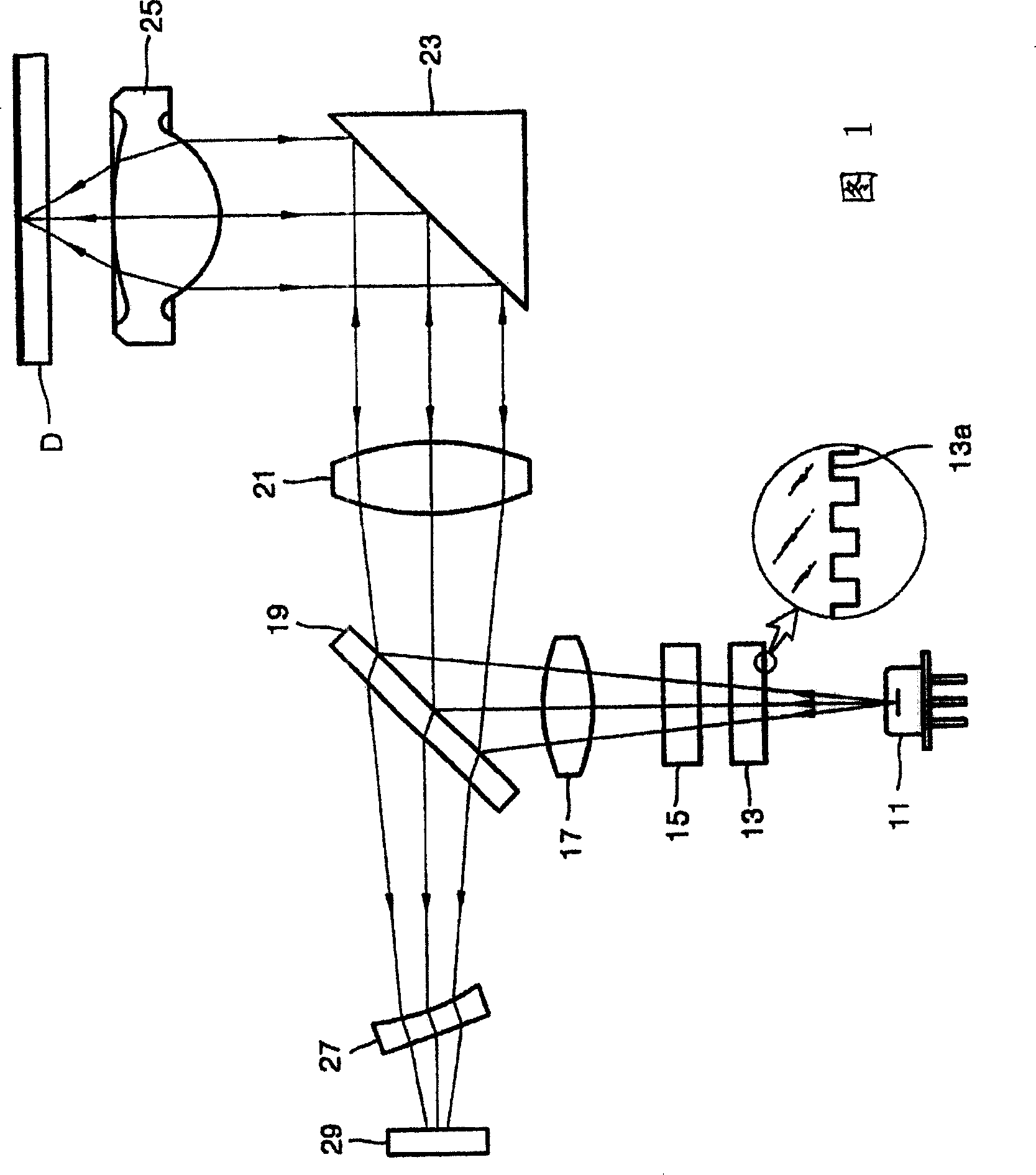
[0009] Since a conventional optical pickup device as structured above includes a plurality of optical elements corresponding to the high-speed and high-density recording medium, the arrangement and assembly of the optical elements are complicated.
In particular, since the grating 13, the wavelength plate 15, and the condenser lens 17 are arranged in a narrow space between the light source 11 and the beam splitter 19, the grating 13, the wavelength plate 15, and the arrangement of the condensing lens 17 is very complicated and their assembly is very tight
In this way, due to the increase of optical elements in the optical pickup device, the thermal reliability of the optical pickup device decreases
Moreover, the cost of the optical pickup device increases due to the cost of manufacturing the optical elements separately

Method used


Image

  • Optical pickup equipment
  • Optical pickup equipment
  • Optical pickup equipment

Examples


Embodiment Construction

[0020] The preferred embodiments of the present invention will be described in detail below, in which examples are described based on the accompanying drawings, in which the same reference numerals represent the same elements. In order to illustrate the present invention, the embodiments are described with reference to the drawings.

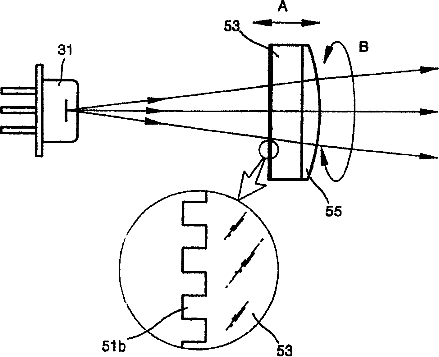
[0021] Referring to FIG. 2, an optical pickup device of the first embodiment of the present invention includes a light source 31 that emits laser light, a beam splitter 36 that changes the propagation path of incident light, and a beam splitter 36 that condenses the incident light into an optical recording medium D. A point objective lens 39, and a photodetector 43 that receives reflected light reflected from the optical recording medium D and then passed through the objective lens 39 and the beam splitter 33.

[0022] According to one aspect of the present invention, the optical path between the beam splitter 33 and the objective lens 39 further inc...


PUM


Abstract

An optical pickup apparatus in which an arrangement and adjustment of optical elements is easy. The optical pickup apparatus includes a light source to emit laser light; a beam splitter to change the travel path of incident light; an objective lens to condense light passed through the beam splitter to form a light spot on an optical recording medium; and a photodetector to receive light reflected from the optical recording medium and then passed through the beam splitter to detect an information signal and an error signal. The optical pickup apparatus further includes a grating for diffraction-transmitting incident light; a wavelength plate to change polarization characteristic of incident light; and an optical output compensating lens to compensate output of light incident from the light source. The grating, the wavelength plate, and the optical output compensating lens are disposed on an optical path between the light source and the beam splitter. At least two of the grating, the wavelength plate, and the optical output compensating lens are formed in one body.

Description

Technical field [0001] The present invention relates to an optical pickup device that records information on or reproduces information from a high-speed and high-density recording medium, and more particularly, relates to an optical element integrally formed so that the optical element can be easily performed Arrangement and adjustment of the optical pickup device. Background technique [0002] Generally, an optical pickup device that records information on or reproduces recorded information on a high-speed and high-density recording medium uses a non-contact method in which light is emitted from a light source. With the development of optical recording media, such as CDs and DVDs, in order to use CDs and DVDs at the same time, the optical pickup device needs to have multiple functions. Moreover, with the development of high-speed and high-density recording media, the structure of the multifunctional optical pickup device has become very complicated. [0003] Referring to Figure ...

Claims


Application Information

Patent Timeline
Patent Type & Authority Patents(China)
IPC IPC(8): G11B7/12G11B7/135G11B7/22
CPCG11B7/1378G11B7/1365G11B7/22G11B7/1353G11B7/1372
Inventor 柳炳烈李东烈
Owner SAMSUNG ELECTRONICS CO LTD
Learn More