
Base structure of camera

A portable and landline technology, applied to cameras, camera bodies, optics, etc., can solve problems such as unreliable reliability, increased weight and volume, and increased operations

Inactive Publication Date: 2008-05-14
于翔
View PDF4 Cites 0 Cited by
  • Summary
  • Abstract
  • Description
  • Claims
  • Application Information

AI Technical Summary

Problems solved by technology

And with the increase of imaging format specifications, the weight and volume also increase sharply, which cannot meet the requirements of portable use
In addition, in the structure of traditional landlines, the front and rear panels or frames are locked on the base or bracket by single-point contact locking of bolts. This single-point locking is actually in an unstable state, and can only be achieved by increasing the bolts. The tightening torque should try to lock the structure as far as possible, which also increases the difficulty of operation under the premise that the reliability cannot be guaranteed

Method used


Image

  • Base structure of camera
  • Base structure of camera
  • Base structure of camera

Examples


Embodiment Construction

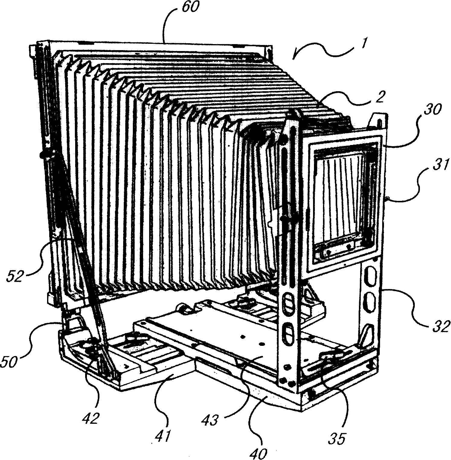
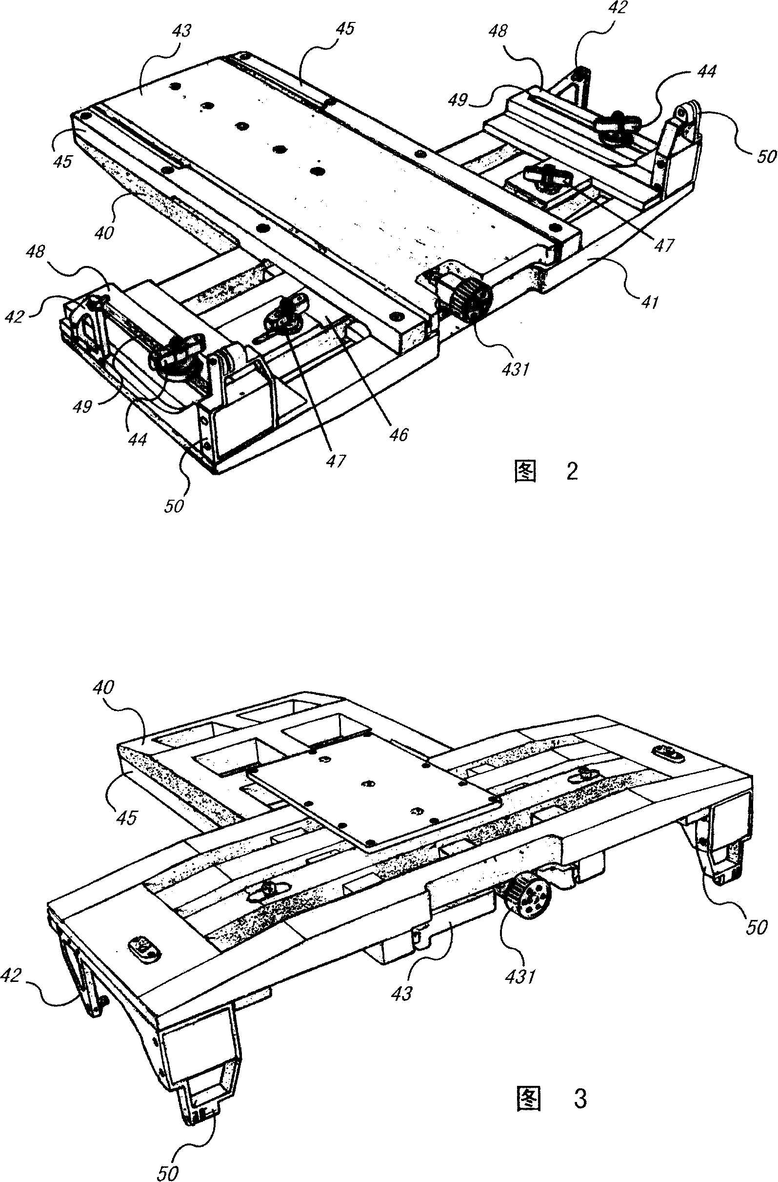
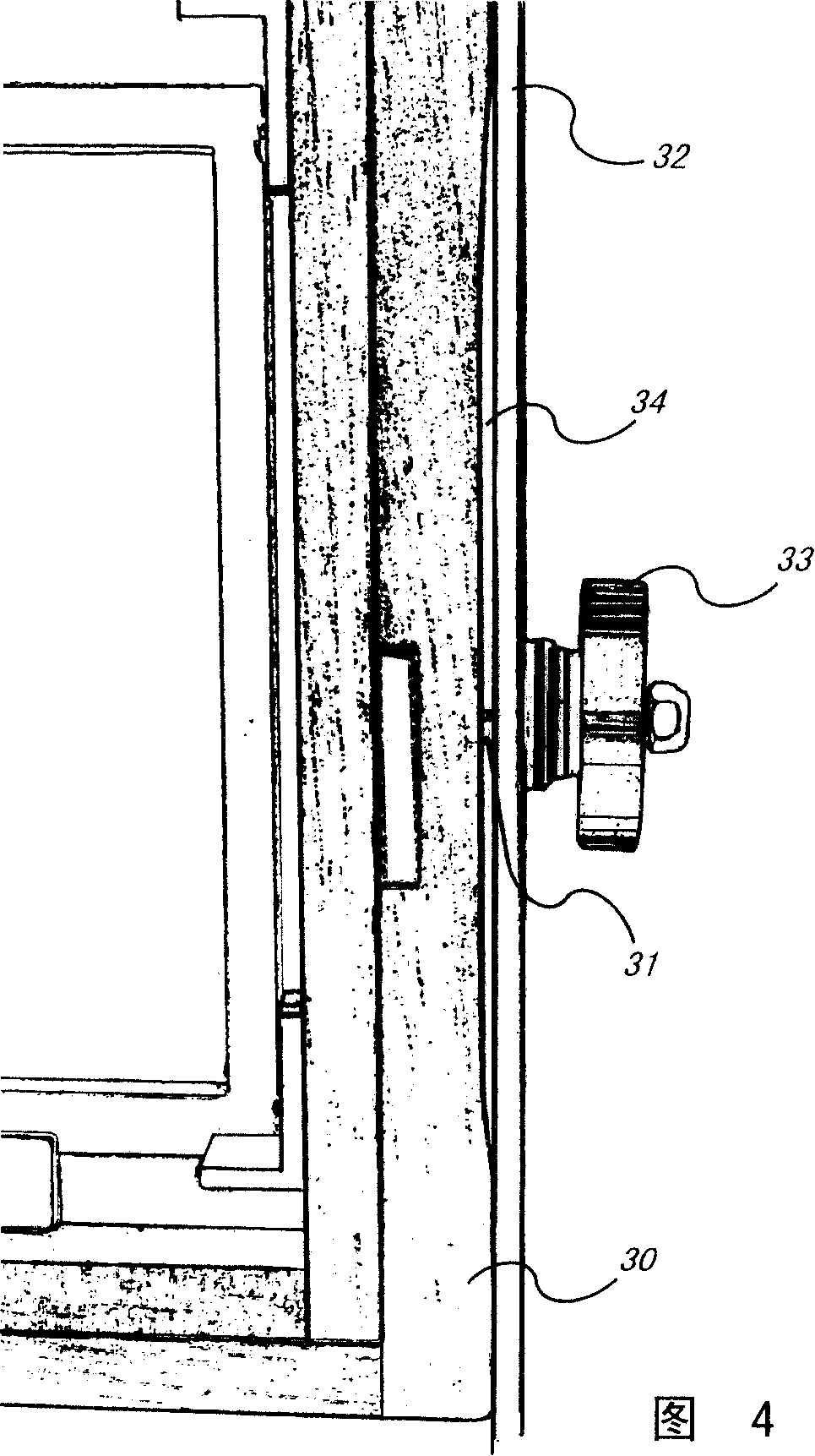
[0015] according to figure 1 To 3, the portable camera landline 1 mainly includes a base, a front group frame 30 , a rear group frame 60 and a bellows 2 . Wherein, the bellows 2 is used to connect the front group frame 30 and the rear group frame 60; the base consists of a base plate 40 and a transverse guide plate 41 to form a “T”-shaped structure, and both sides of the base plate 40 have longitudinal guide rails 45; The longitudinal guide rails 45 can be moved forward and backward together, and can move forward and backward along the longitudinal guide rails 45 through the longitudinal adjustment button 431; the front end of the longitudinal guide plate 43 has a pair of front group arms 32 that can move with the longitudinal guide plate, The group support arm 32 locks the front group support arm 32 on the front end of the longitudinal guide plate 43 through a front group of horizontal locking buttons 35; the front group frame 30 can move up and down and cooperate with the fr...


PUM


Abstract

A studio camera structure consists of base formed by T shaped bottom plate and horizontal guide, a longitudinal guide with track and front support arm coordinating to form frame vertically, a slit having front lifting lock bolt in middle, two back support bases on horizontal guide for supporting back frame, horizontal positioning plate connected to said two back support bases.

Description

technical field [0001] The invention relates to a camera base machine, in particular to a portable camera base machine with reduced weight, increased strength and rigidity, and a more reasonable structure through an improved structural design. Background technique [0002] Today, with the development and change of photographic machinery, camera landlines, stand-alone cameras, still occupy a very important position in the field of photographic machinery with their irreplaceable advantages. The camera landline usually includes a base, a front group frame, a rear group frame and several parts of the bell cavity. The skin cavity constitutes a darkroom. The advantage that it cannot be replaced by other types of camera machinery is that the front and rear panels of the camera base machine can be translated, twisted, or staggered in the front, back, left, right, up, and down directions, and the direction of the horizontal and vertical format can also be changed at will. The bello...

Claims


Application Information

Patent Timeline
Patent Type & Authority Patents(China)
IPC IPC(8): G03B17/04G03B19/02G03B17/02
Inventor 于翔
Owner 于翔
Learn More