Optical gyroscope made from quantum crystal and method for making same

A technology of photonic crystal and optical gyroscope, applied in the field of optical gyroscope, can solve the problems of large device volume, large optical transmission loss, difficult integration, etc., and achieve the effect of improving the accuracy of the gyroscope, solving the large transmission loss and reducing the size of the gyroscope.

Active Publication Date: 2008-04-30
SOUTHEAST UNIV
View PDF5 Cites 0 Cited by
  • Summary
  • Abstract
  • Description
  • Claims
  • Application Information

AI Technical Summary

Problems solved by technology

[0004] Technical problem: the object of the present invention is to propose an optical gyroscope prepared by photonic crystal and its preparation method, and replace the optical gyroscope with traditional optical waveguide structure with photonic crystal waveguide, so as to solve the problems of large volume and difficulty in integration in the prior art. Disadvantages such as large optical transmission loss

Method used


Image

  • Optical gyroscope made from quantum crystal and method for making same
  • Optical gyroscope made from quantum crystal and method for making same

Examples


Embodiment Construction

[0016] The following is a specific implementation manner of implementing an optical gyroscope using a photonic crystal waveguide structure.

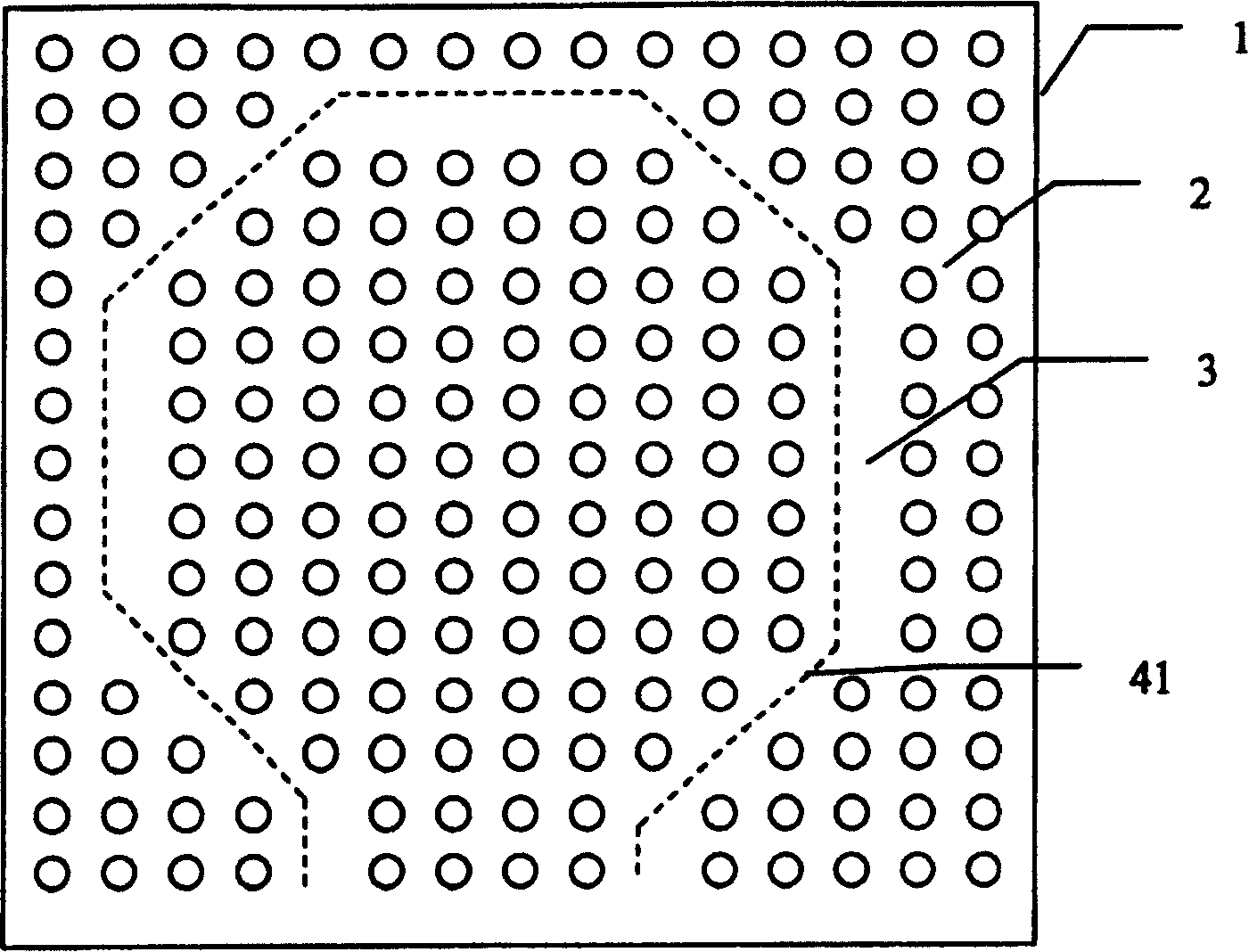
[0017] Both the interference type and the resonant optical gyroscope are based on the Sagnac effect, so that the light beam propagates in the spiral or single ring structure optical waveguide in the opposite direction in the ring waveguide.

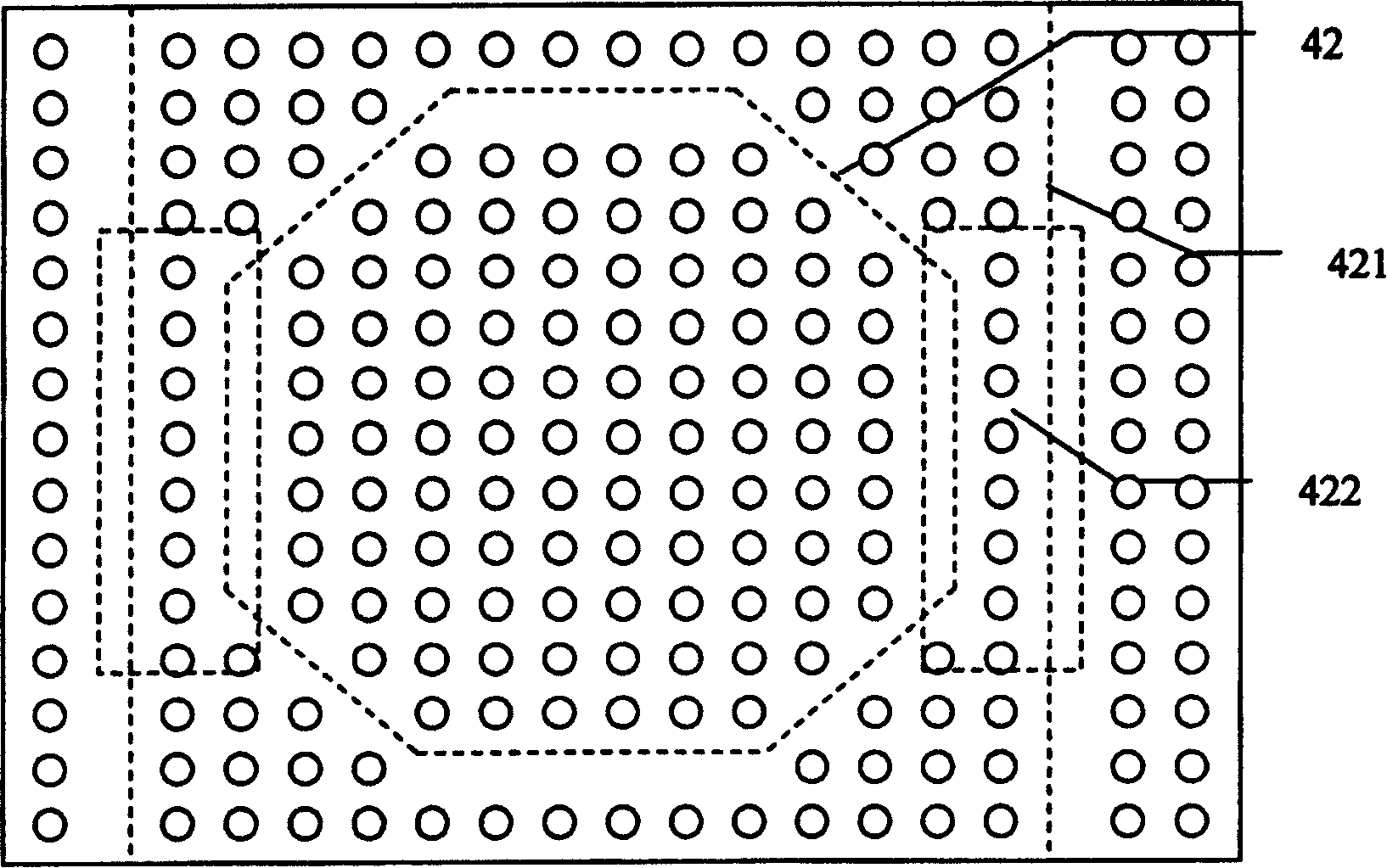
[0018] The optical gyroscope prepared with photonic crystal uses the defect 3 on the photonic crystal 2 of the substrate 1 to make an optical waveguide with low loss, thereby realizing the photonic crystal optical gyroscope, including interference type and resonant type photonic crystal optical waveguide gyroscope; interference type The optical waveguide structure optical gyroscope is composed of an open-loop optical waveguide 41, and the resonant optical waveguide structure optical gyroscope is composed of a closed-loop optical waveguide 42 and a strip waveguide 421 made of defects 3 on the photonic...


PUM


Abstract

This invention relates to phone crystal wave guiding optical top and its process method, which adopts phone crystal to make light wave guiding, which comprises interference and resonance phone crystal wave guiding top. The interference light wave guiding structure is one open light wave and the resonance wave structure top is one loop wave guiding structure. The process method comprises the following steps: a, forming phone crystal wave guiding structure through leading open ring to the interference phone crystal top; b, resonance phone crystal top.

Description

technical field [0001] The invention proposes an optical gyroscope realization scheme with a waveguide structure, in particular to an optical gyroscope with a waveguide structure realized by photonic crystals. Background technique [0002] The optical gyroscope is a new type of photoelectric gyroscope based on the Sagnac effect. The Sagnac effect is a general correlation effect of the propagating light in the closed-loop optical path that rotates relative to the inertial space. After going through the same optical path and traveling in opposite directions, they return to the beam splitting point in the same phase. If there is a rotational angular velocity relative to the inertial space around the axis perpendicular to the plane where the optical path is located, the optical paths traveled by the light beams propagating in the forward and reverse directions are different, resulting in an optical path difference. Theoretically, it can be proved that the optical path differenc...

Claims


Application Information

Patent Timeline
Patent Type & Authority Patents(China)
IPC IPC(8): G01C19/72G01P9/02G02B6/12G01C19/02G01C19/64
Inventor 张彤崔一平
Owner SOUTHEAST UNIV
Why Eureka
Try Eureka