Image compressing method and compressor

An image compression and image technology, applied in the direction of image communication, electrical components, etc., can solve the problems of inability to process compressed image output in real time, increase costs, etc.

Active Publication Date: 2008-02-06
VIA TECH INC
View PDF6 Cites 0 Cited by
  • Summary
  • Abstract
  • Description
  • Claims
  • Application Information

AI Technical Summary

Problems solved by technology

And the capacity of the buffer must have a considerable size to temporarily store 8 or 16 columns of image data, which not only increases the cost, but also makes it impossible to process in real time and output the compressed image while waiting for the data to be transmitted

Method used


Image

  • Image compressing method and compressor
  • Image compressing method and compressor
  • Image compressing method and compressor

Examples


Embodiment Construction

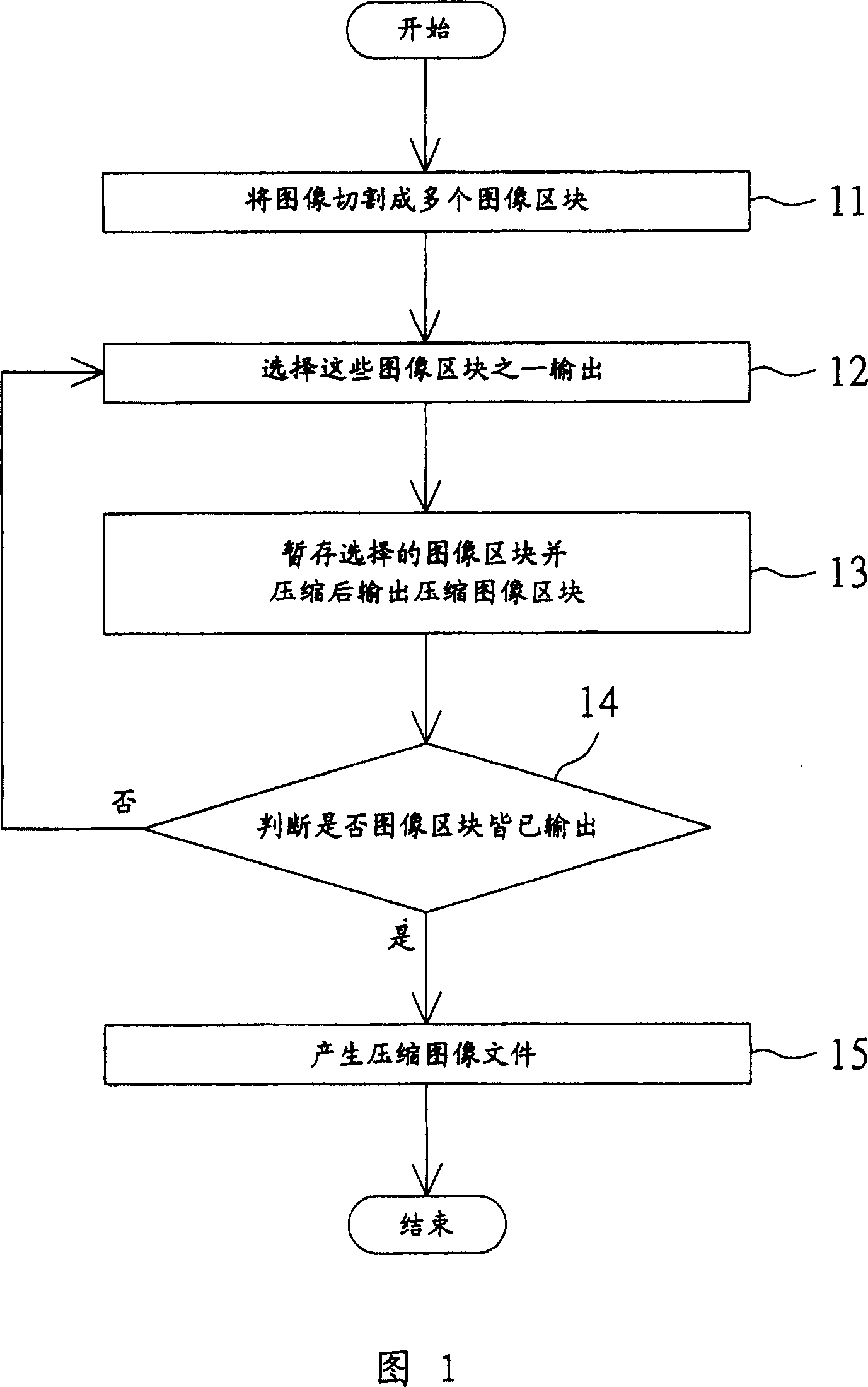
[0023] Referring to FIG. 1 , it is a flowchart of an image compression method according to an embodiment of the present invention. First, cut the image into multiple image blocks, as shown in step 11. The image has A*B pixels, and each image block has N*M pixels, where N is smaller than A and M is smaller than B. Then, an output of these image blocks is selected, for example, the image blocks are sequentially output, as shown in step 12 . Next, the selected image block is temporarily stored and compressed to output a compressed image block, as shown in step 13 . Afterwards, it is judged whether all the image blocks have been compressed to generate multiple compressed image blocks, as shown in step 14, if not, return to step 12. Finally, a compressed image file is generated according to the compressed image blocks, as shown in step 15 .

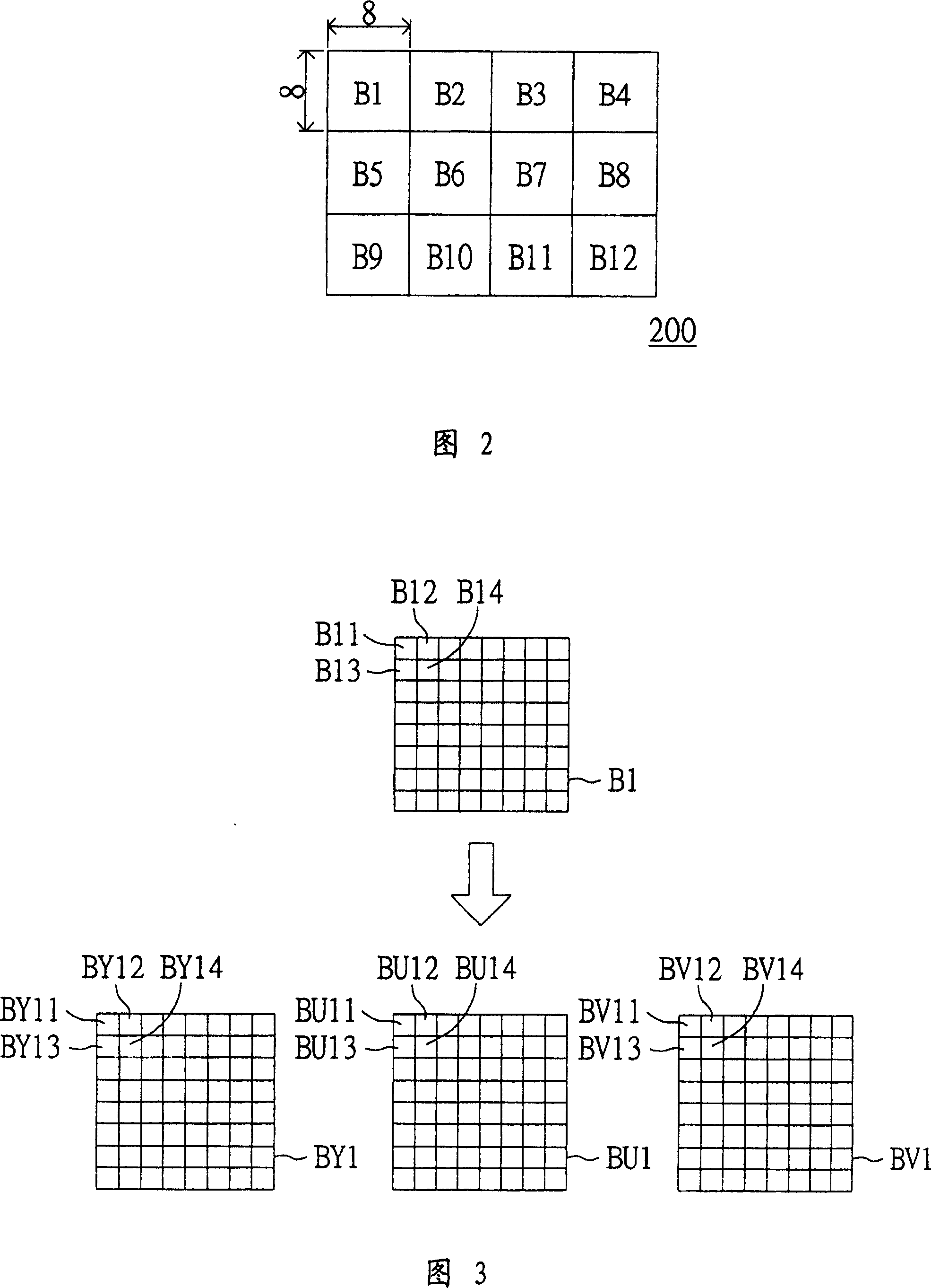
[0024] In step 11, the manner of cutting the image into image blocks refers to FIG. 2 , which is a schematic diagram of cutting an image i...


PUM


Abstract

The method includes following steps: an image is divided into multi image blocks; some of these image blocks are selected and outputted; after the selected image block is temporally saved, it is compressed in order to output it; repeating the above steps, until all image blocks are compressed in order to generate multi compressed image blocks; finally, based on these compressed image blocks, a whole compressed image file is outputted.

Description

technical field [0001] The present invention relates to an image processing device and its method, and in particular to an image compression device and its method. Background technique [0002] When we sample and quantify an original image through an image extraction device, such as a charge-coupled device (CCD) or a complementary metal-oxide semiconductor (CMOS), the data volume of the generated image file is equivalent to Huge, resulting in image processing and data transmission, the processing and transmission speed is slow. Therefore, image compression technology is used to save memory space occupied by image data and to speed up its transmission time. [0003] When image is compressed, the data processing unit is not a one-dimensional image column, but a two-dimensional 8*8 or 16*16 image matrix as a processing unit. However, when data is transmitted to the buffer, it is transmitted in units of columns, and after the image data of one column is transmitted, the image ...

Claims


Application Information

Patent Timeline
Patent Type & Authority Patents(China)
IPC IPC(8): H04N1/41H04N1/64
Inventor 江晋毅黄心威
Owner VIA TECH INC
Why Eureka
Try Eureka