
Zero cross controller of reactive compensator

A compensation device and controller technology, applied in reactive power compensation, reactive power adjustment/elimination/compensation, control/regulation systems, etc., can solve reference voltage waveform distortion, reactive power compensation device burnout, and reactive power compensation device difficulty. Accurately track and adjust problems to achieve the effect of reducing inrush current and overcoming time lag

Inactive Publication Date: 2008-01-09
刘倬云
View PDF4 Cites 0 Cited by
  • Summary
  • Abstract
  • Description
  • Claims
  • Application Information

AI Technical Summary

Problems solved by technology

[0002] Reactive power compensation devices are usually installed in the power supply system, and they usually take the actual voltage on site as the reference voltage to control their switching. Due to the nonlinearity of many load impedances and the large and rapid fluctuations of reactive power loads, the actual on-site Harmonic pollution occurs in the voltage. Due to the distortion of the reference voltage waveform, it is often difficult for the reactive power compensation device to accurately track and adjust, so there will still be an inrush current several times the rated current. In the occasion where frequent switching of the reactive power compensation device is required, it may cause unnecessary Power compensation device burnt out

Method used


Image

  • Zero cross controller of reactive compensator

Examples


Embodiment 1

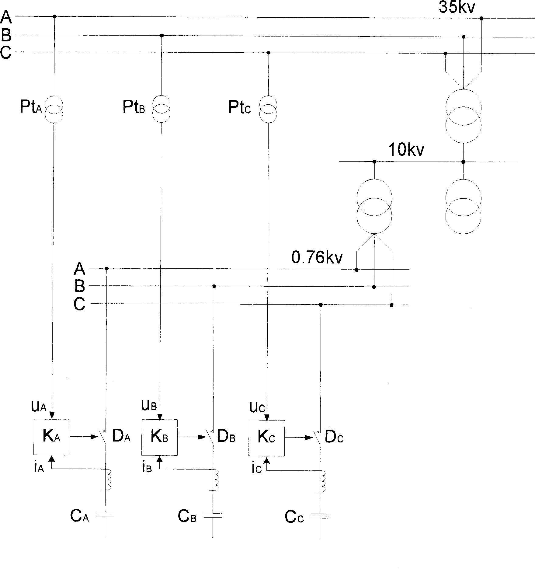
[0007] Embodiment 1: Referring to the accompanying drawings, a zero-crossing controller K of a reactive power compensation device A 、K B 、K C , it K A 、K B 、K C is input with a power frequency reference voltage signal u A , u B , u C , according to which control the low-voltage vacuum circuit breaker D of the corresponding reactive power compensation device A 、D B 、D C The reference switching time is the reference voltage signal u A , u B , u C At a certain moment between 85° and 95°, each controller K A 、K B 、K C is also input into a current signal i of the controlled compensation branch A i B i C , adjust the corresponding low-voltage vacuum circuit breaker D according to the size and direction of the inrush current during switching A 、D B 、D C at the switching moment, the high-frequency non-cycle component in the inrush current value is zero, the inrush current value tends to the fundamental wave value, and the current signal i A i B i C When it is ze...

Embodiment 2

[0008] Embodiment 2: Referring to the accompanying drawings, the zero-crossing controller of the reactive power compensation device, each of the controllers K A 、K B 、K C Both pass through a high voltage sampling transformer Pt A 、Pt B 、Pt C Obtain power frequency reference voltage signal u from 35kv power bus A , u B , u C .


PUM


Abstract

This invention relates to a controller of a reactive compensation device, in which, a working frequency primary voltage signal is input in the controller to control that the primary switch time of a low voltage breaker is a certain time scale of 85-95deg. of the primary voltage signal in related reactive compensation device and a current signal of the controlled compensation branch is input to it to adjust the switch time scale of the related low voltage vacuum breaker based on the diameter and direction of the inrush current when switching to turn the high frequency non-periodic component in the flow value zero and control the cut of the low voltage vacuum breaker when the current signal is zero, which avoids harmonic interference and introduces current signal of the compensation branch for negative feed-back control so as to overcome influence of random factors of time lag.

Description

technical field [0001] The invention belongs to electric equipment, in particular to a controller for controlling switching of a reactive power compensation device. Background technique [0002] Reactive power compensation devices are usually installed in the power supply system, and they usually take the actual voltage on site as the reference voltage to control their switching. Due to the nonlinearity of many load impedances and the large and rapid fluctuations of the reactive power load, the actual on-site Harmonic pollution occurs in the voltage. Due to the distortion of the reference voltage waveform, it is often difficult for the reactive power compensation device to accurately track and adjust, so there will still be an inrush current several times the rated current. In the occasion where frequent switching of the reactive power compensation device is required, it may cause unnecessary Power compensation device burned out. Contents of the invention [0003] The pur...

Claims


Application Information

Patent Timeline
Patent Type & Authority Patents(China)
IPC IPC(8): H02J3/18G05F1/70
CPCY02E40/30
Inventor 刘倬云
Owner 刘倬云
Learn More