Liquid crystal driving system and method

A driving method, liquid crystal driving technology, applied in the direction of instruments, static indicators, etc., can solve problems such as smearing

Active Publication Date: 2008-01-02
AU OPTRONICS CORP
View PDF4 Cites 0 Cited by
  • Summary
  • Abstract
  • Description
  • Claims
  • Application Information

AI Technical Summary

Problems solved by technology

[0011] The main purpose of the present invention is to improve the problem that known liquid crystal panels are prone to smearing in the "dynamic" picture

Method used


Image

  • Liquid crystal driving system and method
  • Liquid crystal driving system and method
  • Liquid crystal driving system and method

Examples


Embodiment Construction

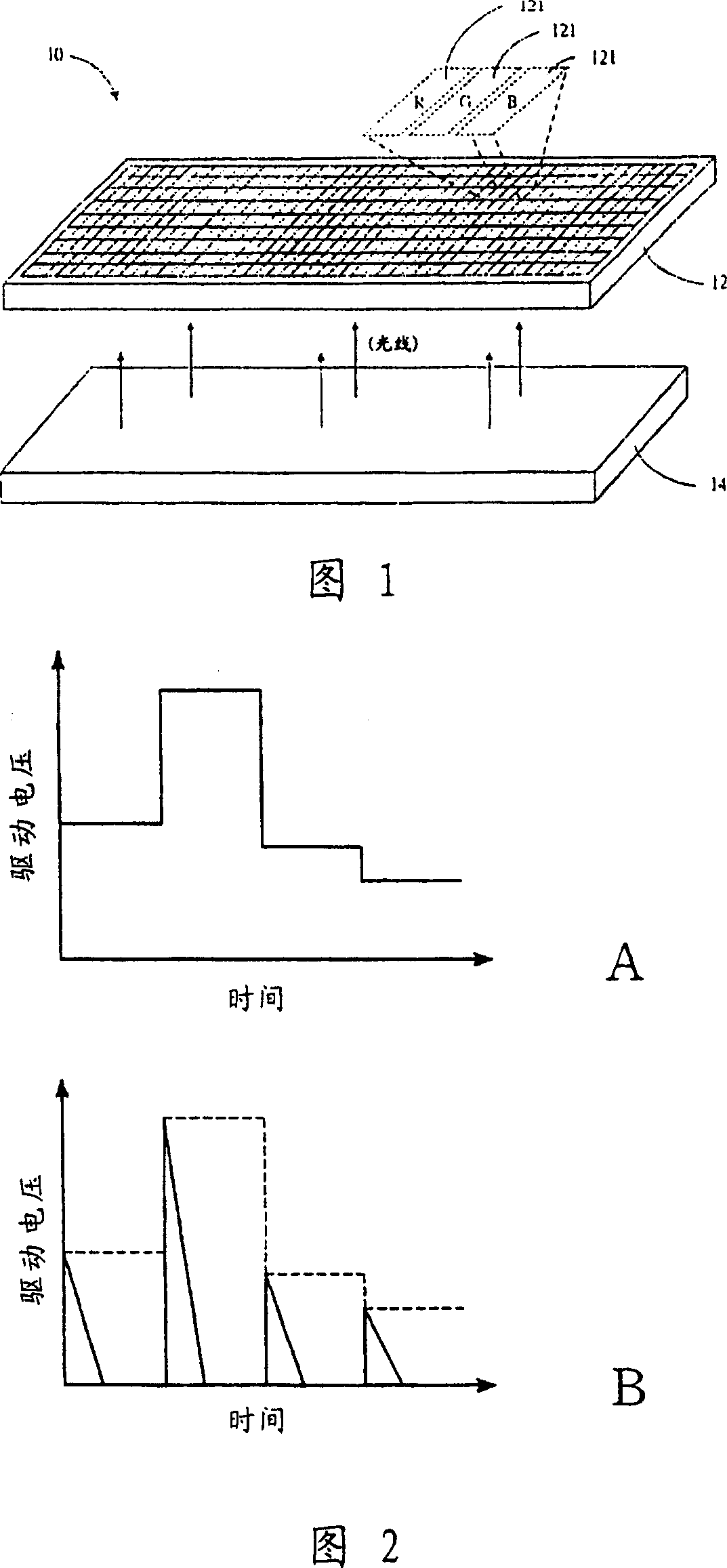
[0042] The present invention intends to provide a perfect solution for the two different situations that the conventional liquid crystal display cannot take into account the "dynamic" and "static" between pictures.

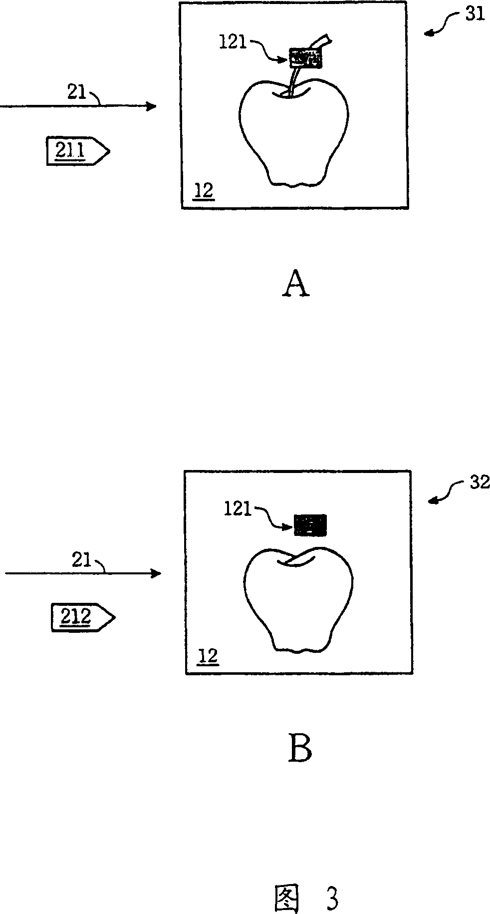
[0043] Please refer to FIG. 3A and FIG. 3B . The liquid crystal panel 12 can display multiple frames. For example, after the liquid crystal panel 12 displays a previous frame 31 , it displays a current frame 32 to continue the previous frame 31 . It is worth noting that since the method of the present invention is related to two adjacent frames, the previous frame and the current frame in the text may represent any two adjacent frames, not just specific frames.

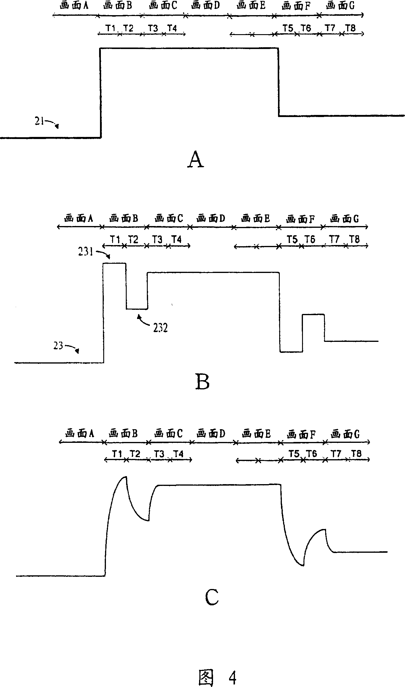
[0044]The contents of multiple frames displayed by the liquid crystal panel 12 depend on an image signal 21 . The image signal 21 may come from a laser disc player (DVD or VCD), a display card of a computer, or other signal sources. The image signal 21 includes predetermined grayscale signals (such as r...


PUM


Abstract

The invention provides a liquid crystal plane driving method. The first presetting grey signal designs the display grey of the element in the front picture; while the second presetting grey signal designs the display grey of the element in the current picture. The driving method comprises: a) comparing weather the second presetting grey signal is equal to the first presetting grey signal. b) If it equals to the first presetting grey signal, it uses a persistent mode to drive the element in the current picture; if not, it uses a pulse mode to drive the element in the current picture.

Description

technical field [0001] The invention relates to a driving method and a driving system of a liquid crystal panel, in particular to a method and a system for driving a liquid crystal panel using an impulse type. Background technique [0002] The main advantage of liquid crystal display is that it is easy to achieve high display resolution and thin display, so it is widely used in notebook computers. Recently, with the continuous development of large-size panels, liquid crystal displays have also become the mainstream of desktop computer displays. [0003] Please refer to FIG. 1 , which is a basic diagram of a liquid crystal display 10 . The liquid crystal panel 12 has a plurality of pixels (pixels) 121 , and by applying a specific driving voltage to the liquid crystal molecules in each pixel 121 , the rotation angle of the liquid crystal molecules can be changed. The liquid crystal molecules have the function of a light valve. By controlling the rotation angle of the liquid c...

Claims


Application Information

Patent Timeline
Patent Type & Authority Patents(China)
IPC IPC(8): G09G3/36G02F1/133
Inventor 谢曜任黎焕欣汪志松
Owner AU OPTRONICS CORP
Why Eureka
Try Eureka