Method for improving display image quality and display device

A technology for a display device and image quality, applied to a method and a display device, to improve the display image quality field, capable of solving problems such as smearing, degradation of panel image quality, and poor appreciation, achieving high-contrast synchronous display, improving asynchronous problems, The effect of improving response time

Pending Publication Date: 2021-06-18
XIANYANG CAIHONG OPTOELECTRONICS TECH CO LTD
View PDF8 Cites 0 Cited by
  • Summary
  • Abstract
  • Description
  • Claims
  • Application Information

AI Technical Summary

Problems solved by technology

[0005] When the LCD panel is driven by voltage, the liquid crystal response time is generally 5-30ms. This response speed has the problem of smearing when displaying dynamic images, resulting in a decrease in the quality of the panel and poor viewing.
The commonly used solution is over-driving or over-voltage driving (OD, Over Driving). This method can improve the response time of the liquid crystal, but it is easy to cause the over-driving voltage to be too high and bright edges to appear. In addition, the current LCD backlight It is always on, and the signal delay of more than ten milliseconds will be noticed by human eyes when displaying dynamic pictures, which will cause picture smear, and derivative problems after OD appears.

Method used


Image

  • Method for improving display image quality and display device
  • Method for improving display image quality and display device
  • Method for improving display image quality and display device

Examples


Embodiment Construction

[0063] The present invention will be described in further detail below in conjunction with specific examples, but the embodiments of the present invention are not limited thereto.

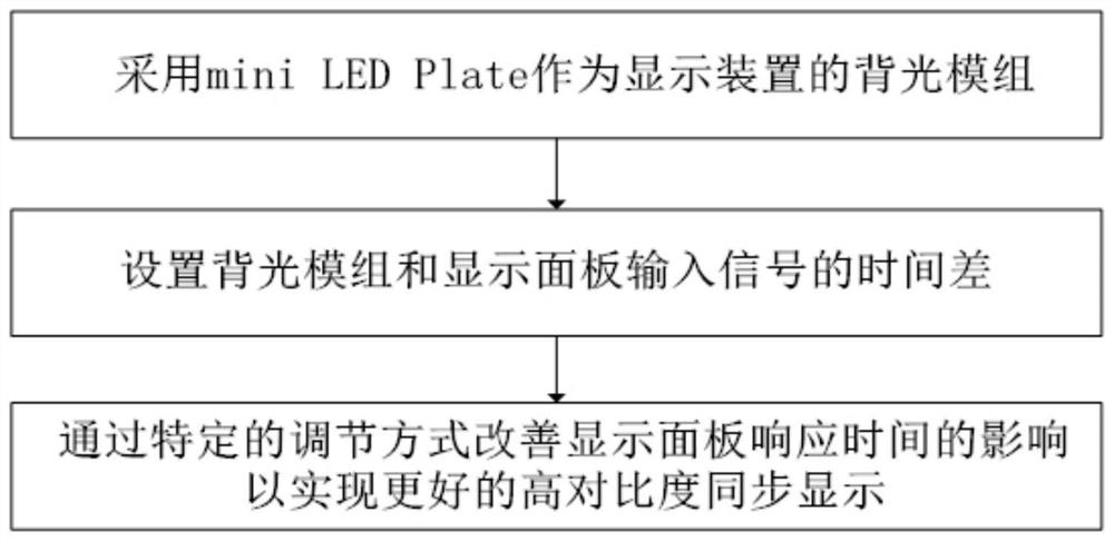
[0064] like figure 1 as shown, figure 1 It is a schematic diagram of steps of a method for improving display quality in an embodiment of the present disclosure; a method for improving display quality provided by an embodiment of the present disclosure includes:

[0065] Using mini LED Plate as the backlight module of the display device or display;

[0066] Setting the time difference between the backlight module and the input signal of the display panel or display device;

[0067] The effect of improving the response time of the display panel or display device through a predetermined adjustment method is used to achieve better high-contrast synchronous display.

[0068] In one embodiment of the present disclosure, as figure 2 as shown, figure 2 It is a schematic diagram of a display in an em...


PUM


Abstract

The invention discloses a method for improving display image quality. The method comprises the following steps: adopting a mini LED as a backlight module of a display device; and setting the time difference of input signals of the backlight module and the display panel. The influence of the response time of the display panel is improved through the preset adjustment mode, so better high-contrast synchronous display is realized. The invention further provides a display device, and the display image quality is improved by adopting the method for improving the display image quality; specifically, the problem of asynchronization caused by slow response time of the LCD is solved, the response time is improved, picture smear and the like are improved, and better high-contrast synchronous display of the display device is achieved.

Description

technical field [0001] The present disclosure relates to the field of display technology, and in particular, to a method for improving display quality and a display device. Background technique [0002] A general liquid crystal display device mainly includes a source drive circuit and a gate drive circuit arranged on a liquid crystal panel (Panel), and a horizontal direction circuit board (X-board, referred to as XB), which is arranged on a system board or a motherboard (Main Board, referred to as MB). System On Chip (SOC for short) and timing controller (Timing Control, TCON for short), are usually connected to the circuit board and the horizontal direction circuit board through a flexible flat cable (Flexible Flat Cable, FFC for short) for two The signal transmission between them, wherein, the system level chip receives the image data signal to be transmitted, and outputs the image data signal to be transmitted, and then processes the input signal through the row expansion...

Claims


Application Information

Patent Timeline
Patent Type & Authority Applications(China)
IPC IPC(8): G09G3/34G09G3/36
CPCG09G3/3406G09G3/36G09G2320/0257G09G3/34G02F1/133G02F1/1336
Inventor 康海燕文欢
Owner XIANYANG CAIHONG OPTOELECTRONICS TECH CO LTD
Why Eureka
Try Eureka