Swirl fluid machinery

A kind of fluid machinery and scroll technology, applied in the direction of rotary piston machinery, mechanical equipment, rotary piston pump, etc., can solve the problems of reduced compression efficiency and increased gap, so as to reduce power loss, improve strength and reduce cost Effect

Active Publication Date: 2008-01-02
HITACHI LTD
View PDF6 Cites 2 Cited by
  • Summary
  • Abstract
  • Description
  • Claims
  • Application Information

AI Technical Summary

Problems solved by technology

Therefore, the gap between the lap portion of the fixed scroll body and the lap portion of the orbiting scroll body on the peripheral surface of the lap portion except for the protrusion is larger than that of the lap portion without the protrusion, so The problem of reduced compression efficiency

Method used


Image

  • Swirl fluid machinery
  • Swirl fluid machinery
  • Swirl fluid machinery

Examples


Embodiment Construction

[0105] Hereinafter, a scroll-type fluid machine according to an embodiment of the present invention will be described in detail with reference to the accompanying drawings, taking a scroll-type air compressor as an example.

[0106] Here, FIGS. 1 to 13 show a first embodiment, and in this embodiment, a configuration in which protrusions are provided on the orbiting scroll will be described as an example.

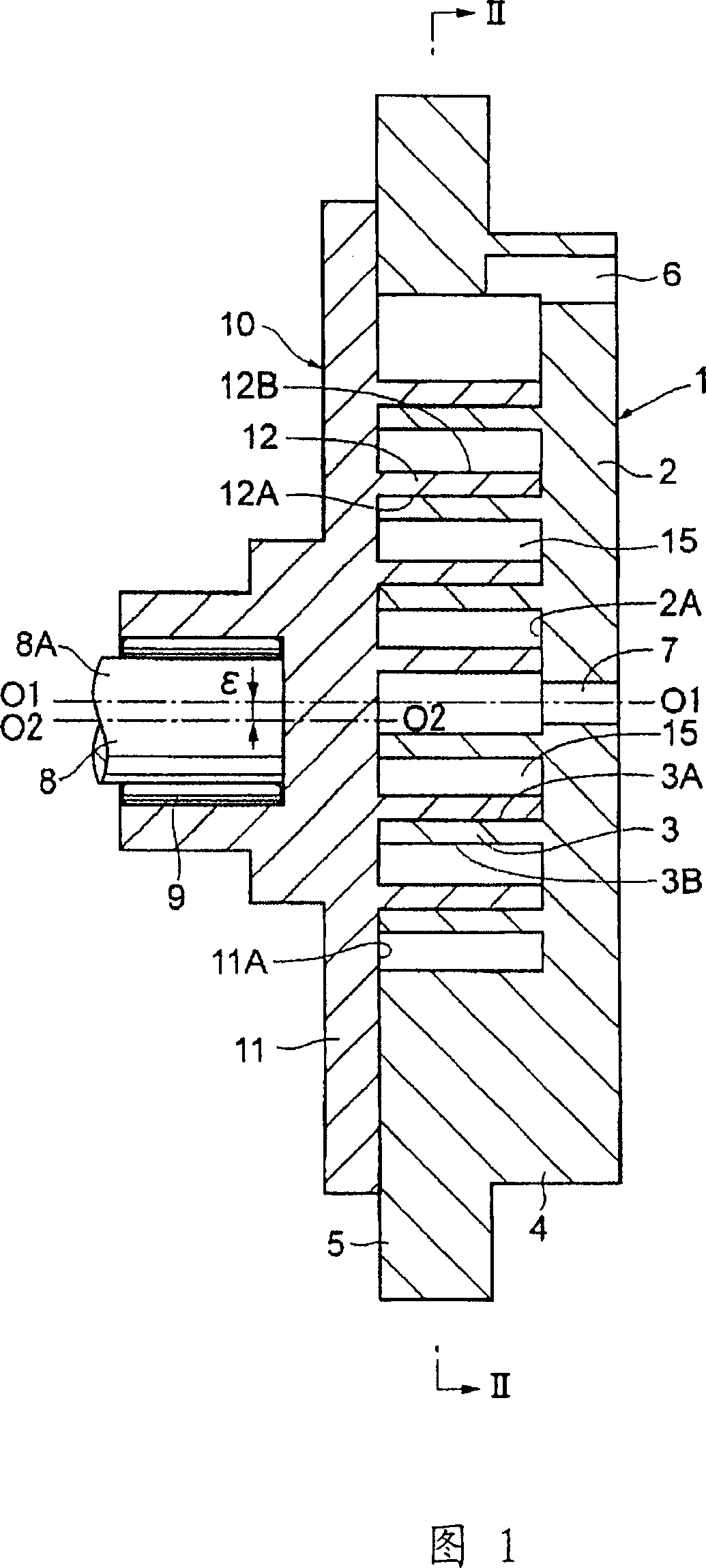
[0107] FIG. 1 shows a longitudinal sectional view of a scroll air compressor. In this FIG. 1, 1 is a fixed scroll body of the scroll air compressor; the fixed scroll body 1 is attached to a cylindrical casing (not shown) end of . In addition, the fixed scroll body 1 includes: an end plate 2 formed in a disc shape, the center of which is aligned with the axis 01-01 of the drive shaft 8 to be described later; The lap portion 3 ; the cylindrical portion 4 that surrounds the lap portion 3 and protrudes in the axial direction from the radial outer side of the end plate 2 ; and t...


PUM


Abstract

The purpose of this invention is to prevent a motive power loss and noise in operation, while enhancing sealability of a compression space, by properly setting its angle, while enhancing strength of projections arranged in a lap part. The inner diameter side projection 13 and the outer diameter side projection 14 are respectively arranged on an inner peripheral surface 12A and an outer peripheral surface 12B of the lap part 12 of a revolving scroll 10, and these cross sections are formed in a substantially triangular shape. Thus, the projections 13 and 14 can enhance the strength by preventing stress concentration by concave circular arc surfaces 13B and 14B, and top parts 13A and 14A can easily become familiar by contacting with the lap part 3. An angle [alpha] formed by the adjacent projections 13 and 14 is set in a predetermined range. Thus, the sealability of the compression space 15 is enhanced, and workability of the lap part 12 and the projections 13 and 14 can be enhanced.

Description

technical field [0001] The present invention relates to a scroll-type fluid machine suitable for use in, for example, air compressors, vacuum pumps, and the like. Background technique [0002] The structure of a general scroll type fluid machine includes: a fixed scroll body; and a rotating scroll body opposite to the fixed scroll body. In addition, each of the fixed scroll body and the orbiting scroll body has a circular plate-shaped end plate, which is rolled in a scroll shape from the radially inner side to the radially outer side of the end plate, and a lap plate provided upright on the end plate in the axial direction. connection. In this way, the fixed scroll body and the orbiting scroll body form a plurality of compression chambers by overlapping the overlapping portions. [0003] Furthermore, in the scroll type fluid machine, by rotating the orbiting scroll at a constant radius of rotation with respect to the fixed scroll through the drive shaft, the gas can be suc...

Claims


Application Information

Patent Timeline
Patent Type & Authority Patents(China)
IPC IPC(8): F04C18/02F04C25/02F04C29/00
Inventor 末藤和孝坂本晋福井宏治三桥博牧岛正夫小林义雄筑间宽水越绫
Owner HITACHI LTD
Why Eureka
Try Eureka