2D shifting unit
A plane moving, flat technology, applied in the direction of generator/motor, piezoelectric effect/electrostrictive or magnetostrictive motor, instrument, etc., can solve the problems of complex control logic, high power consumption, slow moving speed, etc. Achieve the effect of simple control logic, low power consumption and low cost
- Summary
- Abstract
- Description
- Claims
- Application Information
AI Technical Summary
Problems solved by technology
Method used
Image

Examples
Embodiment 1
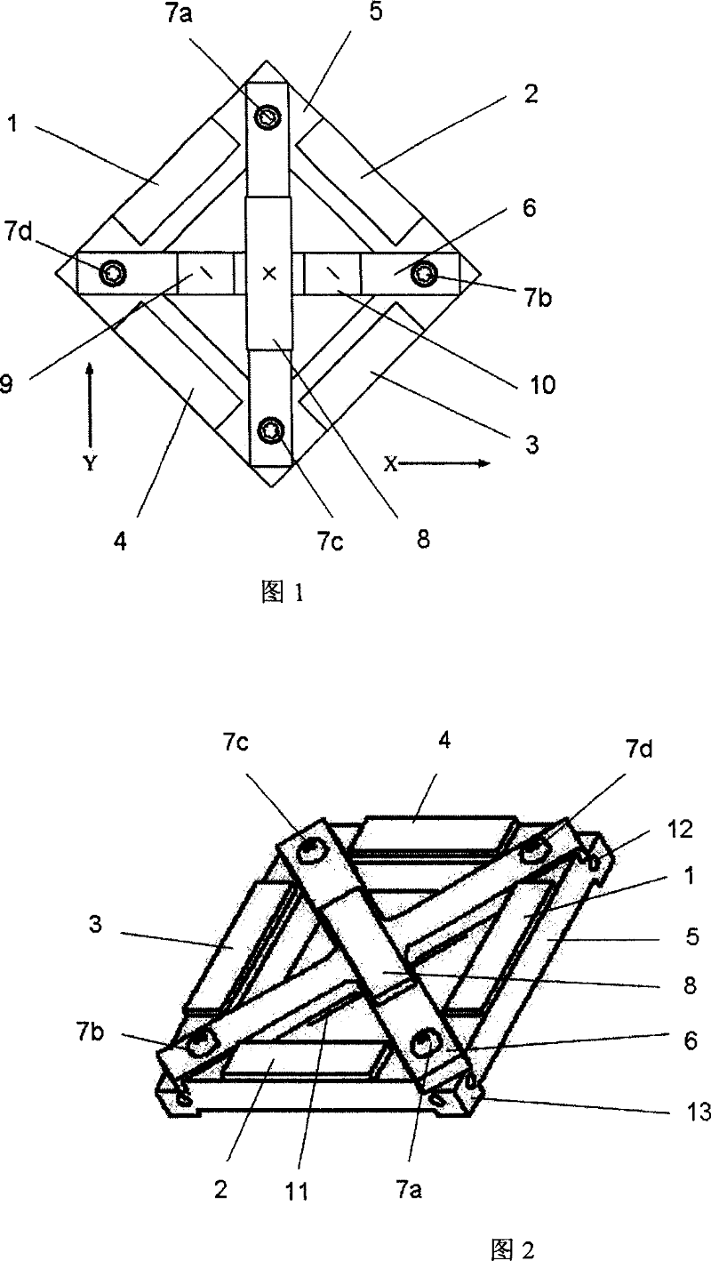
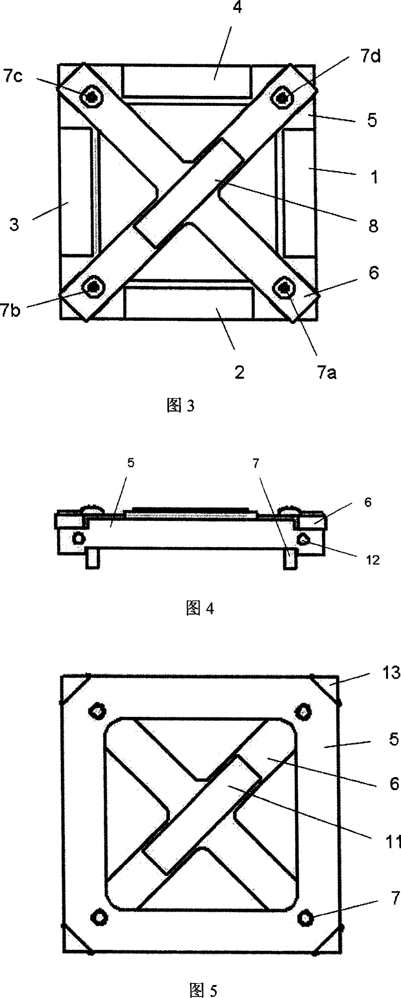
[0044] Embodiment 1: (see Fig. 1, Fig. 2, Fig. 3, Fig. 4 and Fig. 5)
[0045] The present embodiment has the following components: a square flat frame 5, a cross-shaped plate 6, piezoelectric ceramic sheets 1, 2, 3 and 4 pasted around the frame 5, fastening screws 7a, 7b, 7c and 7d, pasted on ten The piezoelectric ceramic sheet 8 on the front side of the glyph plate 6 and the piezoelectric ceramic sheet 11 on its back side.
[0046] On the upper surface of the frame 5, a groove matched with the cross-shaped plate 6 is opened along the diagonal direction, the cross-shaped plate 6 is embedded therein, bonded with epoxy resin at the bottom of the groove, and then fastened with the fastening screw 7. Four piezoelectric ceramic sheets 1, 2, 3 and 4 are polarized along the thickness direction, and are respectively pasted on the middle of the four sides of the upper surface of the frame 5 with epoxy resin, so that the positive directions of polarization of the four piezoelectric cera...
Embodiment 2
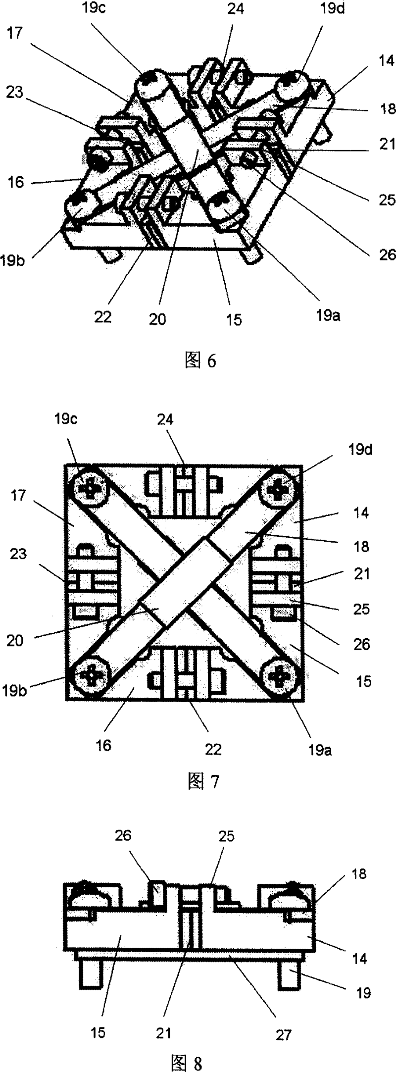
[0048] Embodiment 2: (see Fig. 6, Fig. 7, Fig. 8 and Fig. 9)
[0049] This embodiment has the following components: four completely identical L-shaped frames 14, 15, 16 and 17 cut from a complete square flat frame, cross-shaped plates 18, and clamped by two L-shaped frames. Electric ceramic sheets 21, 22, 23 and 24, fastening screws 19a, 19b, 19c and 19d, clamping screws 26, fixed sheets 27, piezoelectric ceramic sheets 20 pasted on the front of the cross-shaped plate 6 and piezoelectric ceramic sheets on its back side Ceramic sheet28.
[0050] The biggest feature of this embodiment is that the piezoelectric ceramic sheets arranged on the four sides of the square frame are clamped instead of pasted. Its advantages: on the one hand, the overall structure can be miniaturized; on the other hand, the working mode of piezoelectric ceramics is changed from the original transverse mode to the thickness mode, and the electromechanical conversion efficiency is improved. On the upper ...
PUM
 Abstract
Description
Claims
Application Information
 - R&D
- Intellectual Property
- Life Sciences
- Materials
- Tech Scout
- Unparalleled Data Quality
- Higher Quality Content
- 60% Fewer Hallucinations
Browse by: Latest US Patents, China's latest patents, Technical Efficacy Thesaurus, Application Domain, Technology Topic, Popular Technical Reports.
© 2025 PatSnap. All rights reserved.Legal|Privacy policy|Modern Slavery Act Transparency Statement|Sitemap|About US| Contact US: help@patsnap.com