
Minitype jet pump and preparation method

A jet pump and miniature technology, which is applied in the field of micro-actuator, micro-fluid control, and transmission, can solve the problems of complex micro-pump structure and difficult preparation process, and achieve the effect of simple structure, wide selection range and improved stability

Inactive Publication Date: 2007-12-19
PEKING UNIV
View PDF4 Cites 0 Cited by
  • Summary
  • Abstract
  • Description
  • Claims
  • Application Information

AI Technical Summary

Problems solved by technology

[0004] The present invention overcomes the above-mentioned shortcomings of the micro pump such as complicated structure and difficult preparation process, and provides a micro jet pump without additional complicated electric, magnetic, thermal and other driving systems; Microtransport of a fluid

Method used


Image

  • Minitype jet pump and preparation method
  • Minitype jet pump and preparation method

Examples


Embodiment Construction

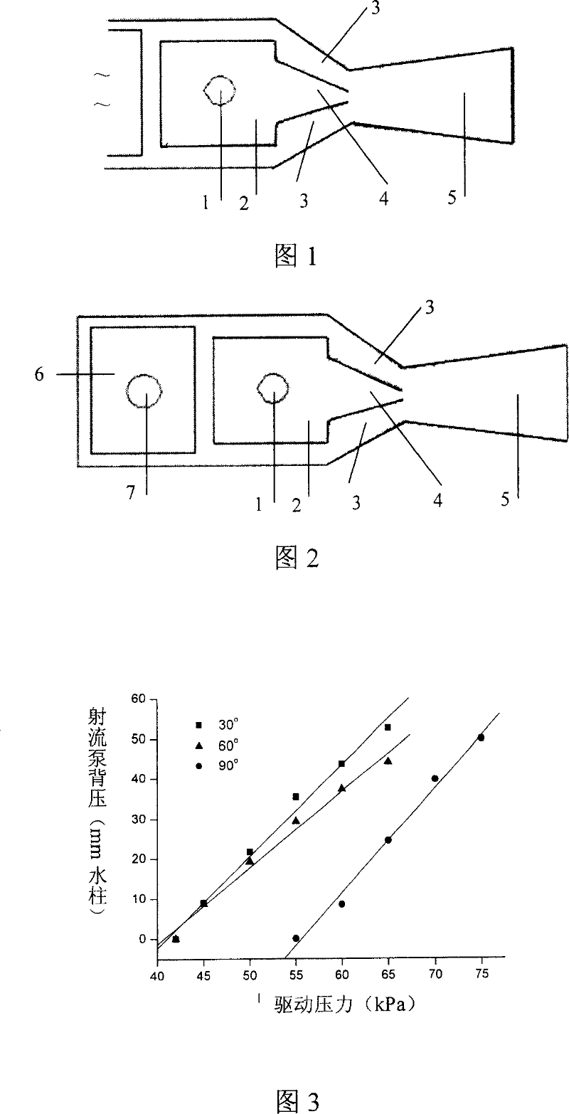
[0032] Fig. 1 is a schematic plan view of the micro jet pump provided by the present invention. The main body of the micro-jet pump includes a driving structure and a suction structure. The driving structure is composed of a jet nozzle 4 and a driving chamber 2 connected thereto, wherein the driving chamber 2 is provided with a driving fluid inlet hole 1, and the driving fluid inlet hole 1 is located at A certain position corresponding to the upper part of the driving chamber 2 is an interface connected with an external pipeline, and the driving chamber 2 may be square, circular or oval. The driving chamber 2 and the jet nozzle 4 together constitute the driving structure for generating the jet. The present invention can also seal the driving cavity 2, process the pump cavity membrane by micromachining, stick a piezoelectric sheet, a magnetic sheet, a shape memory alloy film on it, or add a layer of membrane electrodes on the upper and lower surfaces of the pump cavity, It can...


PUM


Abstract

The invention provides a kind of mini-type jet pump and its preparation method. The pump body includes drive structure and suck structure. The drive structure is made up of ejector nozzle, drive chamber connected to the ejector nozzle; the drive chamber is installed drive liquid inlet hole. The suck structure includes suck entrance end, suck interval channel, and diffusion exit. The ejector nozzle is installed at the diffusion exit; the suck interval channel is installed at the both sides of the ejector nozzle. The high pressure driving gas or liquid is entranced into drive chamber by the drive liquid inlet hole, and jetted with high speed at the exit of the ejector nozzle; as well as, the vortex is appeared at its boundary, the liquid in the suck interval channel is sucked by the vortex scroll to jet; the mixed liquid with the two different flow rate mixed liquid are both flowed into the diffusion exit. The preparation of the mini-type jet pump adopts MEMS technology design to realize by two piece photo etching plate; the selection range of the pump body material is large; and it is easy to integrate with most micro flow system.

Description

technical field [0001] The invention belongs to the technical fields of microfluid control, transmission and microactuator, and in particular relates to a microjet pump designed and manufactured by adopting microelectromechanical system (MEMS) technology. Background technique [0002] Fluid transport in microstructures has always had many problems due to small size, such as residual bubbles in the flow of liquid in microchannels, and the current MEMS micropump is limited by its complex structure, difficult processing and high cost. its wide application. [0003] Micropumps are the core components of microfluidic control systems. Micropumps processed with MEMS technology are mainly divided into mechanical fluid control systems and non-mechanical fluid control systems. Mechanical micropumps mainly include piezoelectric micropumps, electromagnetic micropumps, electrostatic micropumps and Pneumatic micropumps, etc., the common problems of these types of micropumps are complex s...

Claims


Application Information

Patent Timeline
Patent Type & Authority Patents(China)
IPC IPC(8): F04F5/00
Inventor 张大成李修函于晓梅李婷王颖王阳元
Owner PEKING UNIV
Learn More