Clutch device for magnetic recording/reproducing apparatus

a technology of magnetic recording/reproducing apparatus and clamping device, which is applied in the direction of gearing, slip coupling, speed-changing/reversing arrangement, etc., can solve the problems of reducing the operation efficiency of the assembly process, increasing production costs, and increasing production costs due to the large amount of construction parts. , to achieve the effect of reducing production costs, reducing the number of components, and improving assembly operation efficiency

Inactive Publication Date: 2007-06-26
LG ELECTRONICS INC
View PDF13 Cites 0 Cited by
  • Summary
  • Abstract
  • Description
  • Claims
  • Application Information

AI Technical Summary

Benefits of technology

[0033]In order to solve above-mentioned problems, it is an object of the present invention to provide a clutch device for a magnetic recording / reproducing apparatus which is capable of reducing production cost and improving the efficiency of the assembly operation by minimizing the number of components.
[0038]The driving pulley and the up / down gear respectively include an engaging means which enables them to mesh and rotate together when the up / down gear is transferred toward the driving pulley.
[0048]Accordingly, a clutch device for a magnetic recording / reproducing apparatus in accordance with the present invention is capable of reducing a production cost and improving the efficiency of an assembly operation by minimizing the number of components.

Problems solved by technology

However, the above-mentioned conventional magnetic recording / reproducing apparatus has the following problems.
In this use of clutch springs 18, 18′, production costs are increased due to the large amount of construction parts.
In addition, the operation efficiency of the assembly process is reduced.

Method used


Image

  • Clutch device for magnetic recording/reproducing apparatus
  • Clutch device for magnetic recording/reproducing apparatus
  • Clutch device for magnetic recording/reproducing apparatus

Examples


Embodiment Construction

[0056]Hereinafter, the preferred embodiments of a clutch device for a magnetic recording / reproducing apparatus in accordance with the present invention will be described with reference to accompany drawings.

[0057]Although there may be a plurality of embodiments of a magnetic recording / reproducing apparatus in accordance with the present invention, hereinafter the preferred embodiment will be described.

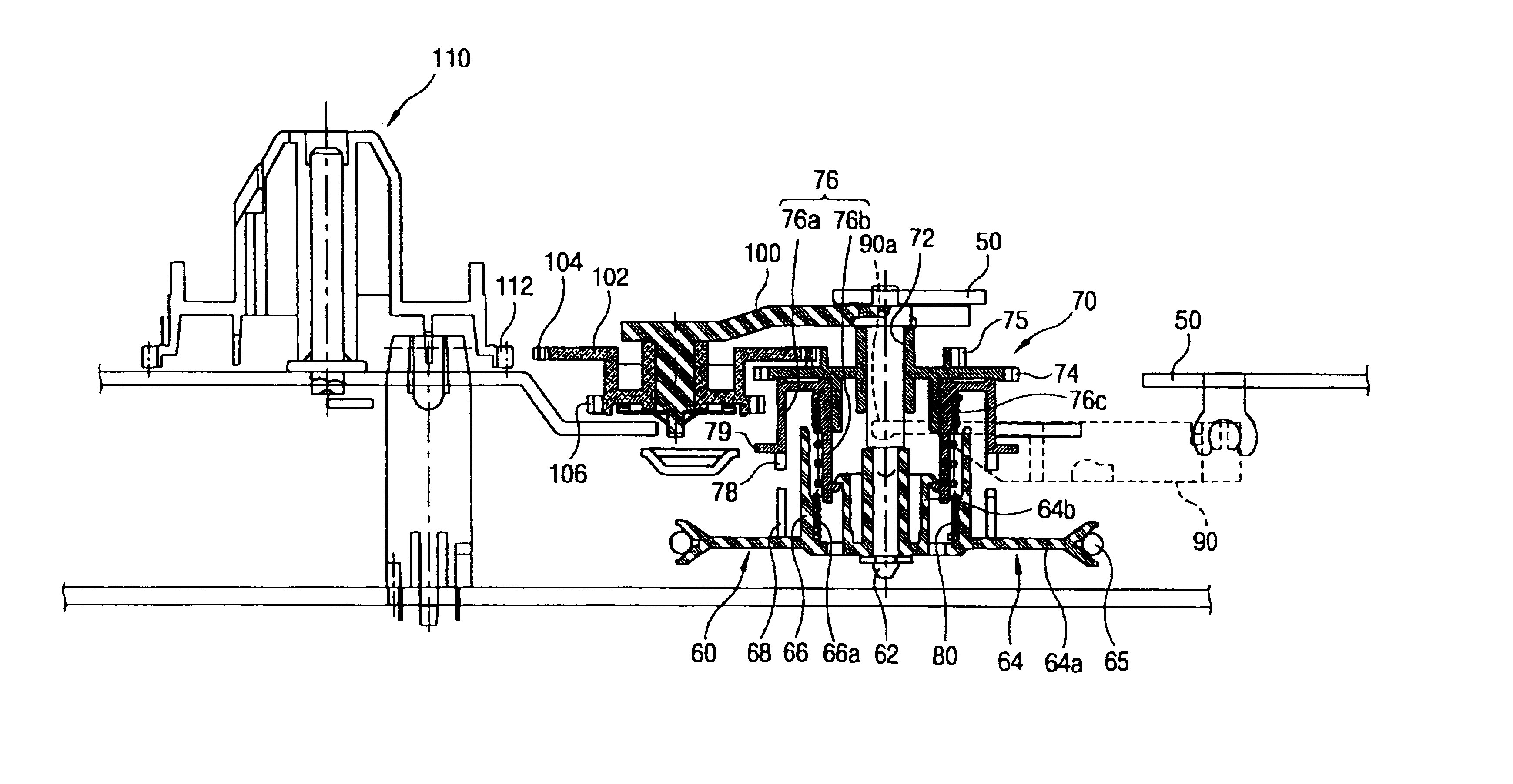
[0058]As depicted in FIG. 4, a clutch assembly 60 is installed on a main chassis 50. In conveying a tape T by transmitting power provided from a capstan motor to a supply reel and a winding reel, the clutch assembly 60 performs the conveyance of the tape T with a regular tension, regardless of the quantity of the tape T wound around the supply reel and winding reel.

[0059]In the structure of the clutch assembly 60, a central shaft 62 is formed on the main chassis 50. A driving pulley 64 is rotatably installed at the central shaft 62. The driving pulley 64 receives power transmitted from...


PUM

PropertyMeasurementUnit
inner diameteraaaaaaaaaa
outer diameteraaaaaaaaaa
torqueaaaaaaaaaa

Abstract

A clutch device for a magnetic recording / reproducing apparatus for transmitting power for a tape conveying regardless of the quantity of tape wound around a reel, including a rotating central shaft installed on a main chassis, a drive pulley connected to the rotating central shaft, and having a cylindrical pulley holder portion, said drive pulley being rotated by receiving power from a driving source, an up / down gear having a cylindrical gear holder unit with the outer diameter thereof being smaller than the inner diameter of the pulley holder portion and ascendable / descendable along the rotatable central shaft, and a clutch spring placed between the inner surface of the pulley holder portion and the outer surface of the gear holder unit for selectively transmitting power with a certain torque from the driving pulley to the up / down gear in accordance with the rotational direction of the driving pulley.

Description

BACKGROUND OF THE INVENTION[0001]1. Field of the Invention[0002]The present invention relates to a magnetic recording / reproducing apparatus, and in particular to a clutch device for a magnetic recording / reproducing apparatus which is capable of transmitting power for regularly conveying a tape, regardless of the quantity of the tape, wound around a reel.[0003]2. Description of the Prior Art[0004]FIG. 1 illustrates a tape path conveying structure of a general magnetic recording / reproducing apparatus.[0005]As shown in FIG. 1, a supplying reel driving body 1 and a winding reel driving body 21 are installed to drive a supplying reel (not shown) and a winding reel (not shown) of a tape cassette (not shown) at one side of a main chassis (C).[0006]A plurality of posts and guide rollers are provided on the main chassis (C) to guide the path of a tape (T) released from a tape cassette.[0007]A tension post 3 for controlling the tensile force of the travelling tape (T) is installed on a tensio...

Claims


Application Information

Patent Timeline
Patent Type & Authority Patents(United States)
IPC IPC(8): G11B15/44F16D13/08
CPCF16D13/08Y10T74/19367
Inventor HONG, SUNG PYOLEE, JI YOUNGCHAE, YOU SEOK
Owner LG ELECTRONICS INC
Why Eureka
Try Eureka